
User's Manual
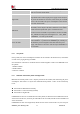
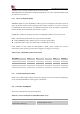
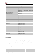
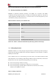
Table Of Contents

Smart Machine Smart Decision
SIM7020G_User Manual_V1.00 41 2019-01-15
pull down resistor)
I
IL
Input low leakage current(no pull
up resistor)
5
uA
*Note: These parameters are for digital interface pins, such as GPIOs (including NETLIGHT,
STATUS, SIM_DET), UART.
The operating temperature of SIM7020G is listed in the following table.
Table 31: Operating temperature
Parameter
Min.
Typ.
Max.
Unit
Normal operation temperature
-30
25
80
℃
Extended operation temperature*
-40
25
85
℃
Storage temperature
-45
25
90
℃
*Note: The performance will be reduced slightly from the 3GPP specifications if the temperature
is outside the normal operating temperature range and still within the extreme operating
temperature range.
6.3 Operating Mode
6.3.1 Operating Mode Definition
The table below summarizes the various operating modes of SIM7020G product.
Table 32: Operating mode Definition
Mode
Function
Normal operation
Sleep mode
In this case, the current consumption of module will be reduced to
the minimal level and the module can still receive paging
message and SMS.
Idle mode
Software is active. Module is registered to the network, and the
module is ready to communicate.
Standby mode
Module is ready for data transmission, but no data is currently
sent or received. In this case, power consumption depends on
network settings.
Data transmission mode
There is data transmission in progress. In this case, power
consumption is related to network settings (e.g. power control
level); uplink/downlink data rates, etc.
Minimum functionality mode
AT command “AT+CFUN=0” AT+CSCLK=1 can be used to set
the module to a minimum functionality mode without removing
the power supply. In this mode, the RF part of the module will not
work and the SIM card will not be accessible, but the serial port