
User's Manual
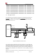
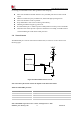


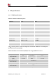
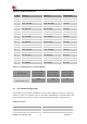
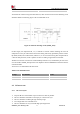
Table Of Contents

Smart Machine Smart Decision
SIM7020G_User Manual_V1.00 34 2019-01-15
3.12 SPI Interface
The SIM7020G provides an SPI interface(master mode), It could be used as SPI interface in the
embedded AT application..
Table 21: Pin definition of the SPI
Pin name
Pin
number
Description
Comment
SPI_MISO
51
Host input and slave output signals
SPI MASTER
Voltage Domain:
1.8V
SPI_MOSI
49
Host outputs slave input signals
SPI_CLK
50
Clock signal generated by the main device
SPI_SS
48
Slave enable signal controlled by master device
SPI interface voltage domain is 1.8v.If the voltage domain of the slave device system is 3.3v, a level
switch shall be added between the module and the slave device Converter; It is recommended to use
a level converter that supports SPI data rate. The reference circuit is shown below:
Module
(DCE)
Translator
GNDGND
VCCA
SPI_SS
SPI_CLK
SPI_MOSI
SPI_MISO
VDD_EXT
A1
A2
A3
A4
DTE
GND
VDD
SPI_SS
SPI_CLK
SPI_MOSI
SPI_MISO
B1
B2
B3
B4
VCCB
GND
0.1uF
0.1uF
0E
Figure 23: SPI interface level conversion reference circuit
Notes:
1. This function is not supported in the standard firmware. If customer wants this function, the
firmware must be customized. Please contact SIMCom for more details.