
User's Manual
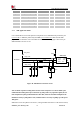
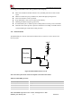


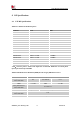
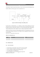
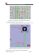
Table Of Contents

Smart Machine Smart Decision
SIM7020G_User Manual_V1.00 30 2019-01-15
Symbol
Parameter
Min.
Typ.
Max.
Unit
SIM_VDD
LDO power output voltage
2.75
3
3.05
V
V
IH
High-level input voltage
0.65*SIM_VDD
-
SIM_VDD +0.3
V
V
IL
Low-level input voltage
-0.3
0
0.25*SIM_VDD
V
V
OH
High-level output voltage
SIM_VDD -0.45
-
SIM_VDD
V
V
OL
Low-level output voltage
0
0
0.45
V
3.7.1 SIM Application Guide
It is recommended to use an ESD protection component such as ESDA6V1W5 produced by ST
(www.st.com ) or SMF15C produced by ON SEMI (www.onsemi.com ). Note that the SIM
peripheral circuit should be close to the SIM card socket. The following figure shows the 6-pin
SIM card holder reference circuit.
MODULE
TVS
SIM_ VDD
SIM_ CLK
SIM_ DATA
SIM_ RST
VCC GND
RST VPP
CLK I/O
22
Ω
100nF
C 707 10M 006 512
SIM Socket
22
Ω
22
Ω
22pF
22pF 22pF
SIM_DET
Figure 19: SIM interface reference circuit
Note: A 100nF capacitor on SIM_VDD is used to reduce interference. For more details of AT
commands about SIM, please refer to document [1].SIM_CLK is very important signal, the rise
time and fall time of SIM_CLK should be less than 40ns, otherwise the SIM card might not be
initialized correctly. If SIM_DET is used, a 10KΩ resistor is necessary to pulling up to the power
VDD_EXT.
SIM card circuit is susceptible to interference, causing the SIM card failures or some other situations,