
User's Manual
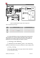
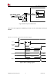
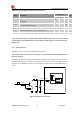
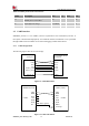
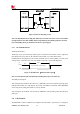
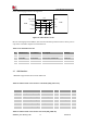
Table Of Contents

Smart Machine Smart Decision
SIM7020G_User Manual_V1.00 28 2019-01-15
VDD_EXT
4.7K
47K
4.7K
DTE
UART1_RXD
MODULE
DCE
VDD_EXT
TXD
VDD
Figure 16: RX level matching circuit
Note: The default band rate is 0bps (auto baud rate). The triode conversion circuit is not suitable
for high band rate more than 460800. When using UART2 for downloading software, the band
rate is 921600bps, please pay attention to the device’s speed support.
3.5.2 RI and DTR Behavior
The RI pin description:
The RI pin can be used to interrupt output signal to inform the host controller such as application
CPU. Before that, users must use AT command “AT+CFGRI=1” to enable this function.
Normally RI will keep high level until certain conditions such as receiving SMS, or a URC report
coming, then it will output a low level pulse 120ms, in the end, it will become high level.
Idle
HIGH
LOW
Receiving SMS reports coming
RI
120ms
Figure 17: RI behaviour (SMS and URC report)
Note: For more details of AT commands about UART, please refer to document [1].
The DTR pin description:
After setting the AT command “AT+CSCLK=1”, SIM7020G will enter sleep mode by pulling up the
DTR pin when module is in idle mode. In sleep mode, the UART is unavailable. When SIM7020G
enters sleep mode, pulling down DTR can wake up module.
After setting the AT command “AT+CSCLK=0”, SIM7020G will do nothing when the DTR pin is
pulling up.
3.6 USB Interface
The SIM7020G contains a USB interface compliant with the USB1.1 specification as a peripheral,