
User's Manual
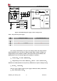
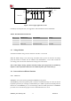
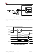
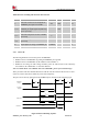
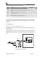
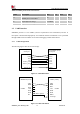
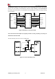
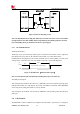
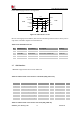
Table Of Contents

Smart Machine Smart Decision
SIM7020G_User Manual_V1.00 26 2019-01-15
Table 12: RESET pin electronic characteristic
Symbol
Description
Min.
Typ.
Max.
Unit
T
reset
The active low level time impulse on
RESET pin to reset module
40
-
-
ms
V
IH
Input high level voltage
0.7*VBAT
V
V
IL
Input low level voltage
0.3*VBAT
V
3.5 UART Interface
SIM7020G provides a 7-wire UART1 (universal asynchronous serial transmission) interface as
DCE (Data Communication Equipment). AT commands and data transmission can be performed
through UART1 interface.UART2 can be used for debugging and download software.
3.5.1 UART Design Guide
The following figures show the reference design.
TXD
RXD
RTS
CTS
UART _DTR
UART _DCD
UART1_RI
TXD
RXD
RTS
CTS
DTR
DCD
RING
MODULE (DCE)
CUSTOMER (DTE)
Serial portSerial port
Figure 12: UART full modem
MODULE
( DCE)
HOST
(DTE)
UARTUART
TXD
RXD
RTS
CTS
DTR
DCD
RI
TXD
RXD
RTS
CTS
DTR
DCD
RING
Interrupt
Wake up host
Figure 13: UART null modem