
User's Manual
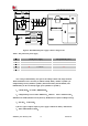
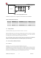
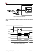
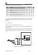
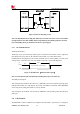
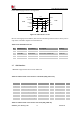
Table Of Contents

Smart Machine Smart Decision
SIM7020G_User Manual_V1.00 22 2019-01-15
VBAT
VBAT
GND
Module
5.1V
500
mW
VBAT
Cb
100uF
100pF
Ce Cc
100uF
Ca
Cd
100nF
22pF
GND
Figure 7: Power supply application circuit
In addition, for ESD protection, it is suggested to add a TVS diode near the VBAT PINs.
Table 9: Recommended TVS diode list
No.
Manufacturer
Part Number
Package
1
Prisemi
PESDHC2FD4V5B
DFN1006
2
Prisemi
PESDHC3D3V3U
SOD323
3
WILLsemi
ESD5651N-2/TR
DFN1006
3.3 Voltage Monitor
To monitor the VBAT voltage, the AT command “AT+CBC” can be used.
When the VBAT voltage is out of the range, the module will be power off when the overvoltage
power-off function is enabled. The AT command “AT+CBATCHK=1” can be used to enable the
overvoltage power-off function and the under-voltage power-off function.
Note: Under-voltage warning function and under-voltage power-off function are disabled by
default. For more information about these AT commands, please refer to Document [1].
3.4 Power on/Power off/Reset Function
3.4.1 Power on
SIM7020G can be powered on by pulling the PWRKEY pin to ground.
The PWRKEY pin has been pulled up with a resistance to VBAT internally, so it does not need to
be pulled up externally. It is strongly recommended to put a 100nF capacitor and an ESD protection
diode close to the PWRKEY pin, as it would strongly enhance the ESD performance of PWRKEY
pin. Please refer to the following figure for the recommended reference circuit.