
User's Manual
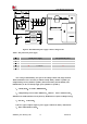
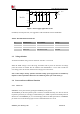
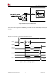
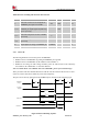
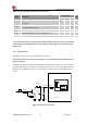
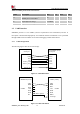
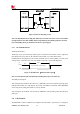
Table Of Contents

Smart Machine Smart Decision
SIM7020G_User Manual_V1.00 21 2019-01-15
Table 8:VDET+PMOS&LDO & diode:
VDET+PMOS
2A LDO DC TPS7A92
2A Diode
MBR2H200SF
Cost
Mediate (Good)
high
less (BEST)
Solution Size
6.45mm2
6.25mm2 (only TPS7A92)
4.455mm2
VBAT operating range
Vmin: 2.1V
Vmax: 3.8V (Good)
Vmin: 2.36V(=2.1V+Vdo)
Vmax: 3.8V
Vmin: 3.0V(2.1V+0.9V@1A)
Vmax: 3.8V (Bad)
Efficiency @Vin > 3.3V
Ploss = 0.75V(Vf@1A) * 1A = 0.75W
Ploss = (3.8V-3.3V) * 1A = 0.5W
Ploss = 0.9V(Vf@1A) * 1A =
0.9W
Efficiency @Vin < 3.3V
Ploss = Ron(<0.125ohm) * 1.652(A) < 0.34W(Good)
Ploss = 0.26V * 1.65A = 0.429W
Ploss = 0.9V * 1.65A = 1.485W
Current consumption
impact
MAX < 0.9Ua
(Good)
2.8mA=> 2.1mA(ground current)+0.7mA(VFB leakage)
(Bad)
No extra current consumption
(BEST)
Comprehensive evaluation: VDET+PMOS is recommended.
LDO solution: LDO current capacity and low Iq are a compromise, and it is not competitive
in performance and cost.
Schottky diode solution: price should be at an advantage but minimum input voltage should
be at 3V at VBAT.
The power supply range of SIM7020G is from 2.1V to 3.6V.Recommended voltage is 3.3V. The
transmitting burst will cause voltage drop and the power supply must be able to provide sufficient
current up to 760mA@2.1V,Make sure that the voltage on the VBAT pins will never drop below
2.1V, or module will work abnormally.
Note: SYSTEM CURRENT EVALUAATE:
①system current=② PA current +③baseband current=760mA:
②Max.PA input current=400mA;
③Max.baseband current=20mA(Without other device on system);
If boost converter efficiency 85%;calculate boost input
current=(400mA*3.3V)/0.85/2.1V=740mA; *Boost output=3.3V/battery min.=2.1V.
Note: Battery pulse current capability should be confirmed with battery vender. SELECT
BATTERY CURRENT CAPABILITY >760mA
Based on the recommendations, the following combination is placed near the VBAT capacitance,
near the module VBAT input, suggested to parallel a low ESR (ESR) = 0.7 Ω 100 uF Ca and Cb
tantalum capacitor, and Cc 100 nF, Cd 100 pF(0402 size) and Ce22pF (0402 size) filtering
capacitance, To improve RF performance and system stability .These capacitors should be put as
close as possible to VBAT pads. Also, users should keep VBAT trace on circuit board wider than 1
mm to minimize PCB trace impedance.