
User's Manual
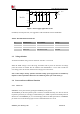
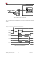
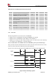
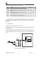
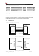
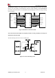
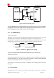
Table Of Contents

Smart Machine Smart Decision
SIM7020G_User Manual_V1.00 20 2019-01-15
BOOST
①system current
SIM7020G
module
PA
Baseband
RF
PMU
②PA current
③baseband current
⑵
⑴
VDET@3.3V
VBAT
Li-SOCl2
Li-MnO2
DC(LDO/DC-DC)
Ⅲ
Ⅰ
Ⅱ
+ +
Ca Cb
Cc
Cd Ce
0402 0402 0402
⑶
0R
VBAT
Surge TVS
MBR2H200SF
OUT
MCH3374
GND
VDD
NC
S-1000C33
4
3
2
1
Figure 6: Recommended power supply reference design circuit
Table 7: The path of the power supply
号
VBAT power supply
The path of the power
1
Ⅰ Li-MnO2
⑴
2
Ⅱ DC (LDO/DC-DC)
⑴
3
Ⅲ Li-SOCl2
⑵
4
Ⅲ Li-SOCl2
⑶
Note: Using Li-SOCl2 battery, the open circuit voltage is about 3.8v, larger than the
VBAT maximum 3.6v.It is necessary to add the schottky diode ( column 3 of table 7) or
voltage limiting circuit (column 4 of table 7) between the battery and the module, and
lithium battery or DC can directly supply power (column 1/2 of table 7).
1
、
schottky diode
:
On-SEMI , MBR2H200SF
;
2
、
voltage limiting circuit: VDET+PMOSFET
:
VDET IC Seiko S-1000C33-I4T1U
,
PMOSFET:On-SEMI ,MCH3374-TL-E (Pb-Free), MCH3374-TL-W (Pb-Free/Halogen Free)
;
3
、
LDO DC
:
TI TPS7A92
;
If the use of power adapter output 5V power supply or lithium ion battery: RT5707WSC
4
、
VDET+PMOS&LDO & diode
: