
User's Manual
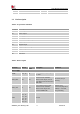
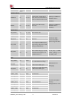
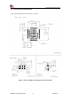
Table Of Contents

Smart Machine Smart Decision
SIM7020G_User Manual_V1.00 19 2019-01-15
3 Interface Application
3.1 Power Supply
The power supply for SIM7020G must be able to provide sufficient instantaneous current up to
more than 760mA@2.1V in order to satisfy the power supply current for maximum consumption.
Table 6: VBAT pins electronic characteristic
Symbol
Description
Min.
Typ.
Max.
Unit
VBAT
Module power voltage
2.1
3.3
3.6
V
I
VBAT(peak)@3.3V
Module power peak current in NB emission
500
-
-
mA
I
VBAT(average)
Module power average current in normal mode
Please refer to the table 32
I
VBAT(sleep)
Power supply current in sleep mode
I
VBAT(PSM)
Power supply current in PSM mode
-
3.4
-
uA
I
VBAT(power-off)
Module power current in power off mode.
-
-
12
uA
3.2 Power Supply Design Guide
In the design of the user, special attention must be paid to the design of the power supply to
ensure the stable operation of the module.SIM7020G can support the use of Li-MnO2 battery,
DC (LDO/ DC-DC), Li-SOCl2 battery and other external power supply, such as its reference
design.
Note: If the power supply for VBAT pins can support up to500mA@3.3V, using a total of more
than 100uF capacitors is recommended, or else users must using a total of 300uF capacitors
typically, in order to avoid the voltage drop. The module power peak current depends on the total
capacitance. Using a total of 1000uF capacitors in the test that will reduce the peak current to
320mA.