
User's Manual
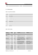
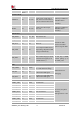
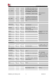
Table Of Contents

Smart Machine Smart Decision
SIM7020G_User Manual_V1.00 15 2019-01-15
RTC_GPIO0
11
DO
In PSM mode, RTC_GPIO0
will change state from low to
high when RTC_EINT receive
an interrupt event to exit PSM.
Enter PSM(RTC_GPIO0 is low)
Exit PSM (RTC_GPIO0 is high)
Voltage Domain:
VBAT
RTC_EINT
12
DI、PU
RTC_EINT can be used to wake
up SIM7020G from PSM mode,
which is pull up to VBAT, active
is low.
GPIO
NETLIGHT
41
DO
LED control output as network
status indication.
If unused, keep them
floating.
Voltage Domain: 1.8V
STATUS
42
DO
Operating status output.
High level: Power on and
firmware ready
Low level: Power off
GPIO0
10
IO
Do not pull down before power
on
GPIO1
29
IO
GPIO2
57
IO
GPIO3
58
IO
GPIO4
59
IO
I2C interface
SDA
64
I/O
Open drain output
If these pins are
unused, keep floating.
SCL
65
I/O
Open drain output
SPI interface
SPI_MISO
51
DI
Host input and slave output
signals
SPI MASTER
If these pins are
unused, keep floating.
Voltage Domain: 1.8V
SPI_MOSI
49
DO
Host outputs slave input signals
SPI_CLK
50
DO
Clock signal generated by the
main device
SPI_SS
48
DO
Slave enable signal controlled
by master device
RF interface
ANT
32
AI
antenna
Other interface
ADC
38
AI
Analog-digital converter input.
Voltage range: 0.1-1.4V.
If unused, keep them
floating.
ADC2
56
AI
NC
20
No connection.
Keep it floating