
User's Manual
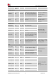
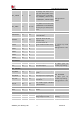
Table Of Contents

Smart Machine Smart Decision
SIM7020G_User Manual_V1.00 14 2019-01-15
66、67、
69-73
System Control
PWRKEY
39
DI,PU
System power on/off control
input, active low. The efficient
input level must be below 0.5V.
PWRKEY has been
pulled up to VBAT via
40Kohm resistor
internally.
RESET
28
DI,PU
System reset control input,
active low.
RESET has been
pulled up to VBAT via
40Kohm resistor
internally.
SIM interface
SIM_DATA
15
I/O,PU
SIM Card data I/O
All lines of SIM
interface should be
protected against ESD.
SIM_RST
17
DO
SIM Reset
SIM_CLK
16
DO
SIM clock
SIM_VDD
18
PO
Power output for SIM card, its
output Voltage depends on SIM
card type automatically.
SIM_DET
14
DI
SIM card detecting input. (This
function do not support yet in
standard software.)
If used, keep a 100kΩ
resistor pulling up to
the VDD_EXT
USB
USB_VBUS
24
DI,PD
Valid USB detection input with
2.5~5.25V detection voltage
USB interface for
debugging
USB_DP
25
I/O
Positive line of the differential,
bi-directional USB signal.
USB_DM
26
I/O
Negative line of the differential,
bi-directional USB signal.
UART interface
UART1_TXD
1
DOH
Transmit Data
If unused, keep them
floating.
Voltage Domain: 1.8V
UART1_RXD
2
DI,PU
Receive Data
UART1_RTS
3
DI,PU
Request to send
UART1_CTS
4
DOH
Clear to Send
UART1_DCD
5
DOH
Data carrier detect
UART1_DTR
6
DI,PU
Transmit Data
UART1_RI
7
DOH
Ring Indicator
UART2_TXD
22
DOH
Transmit Data
UART2_RXD
23
DI,PU
Receive Data
Indicate and Control in PSM Mode