
User's Manual
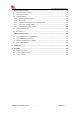

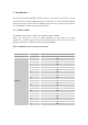
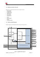
Table Of Contents

Smart Machine Smart Decision
SIM7020G_User Manual_V1.00 9 2019-01-15
1.2 Hardware Interface Overview
The interfaces are described in detail in the next chapters include:
➢ Power Supply
➢ USB Interface
➢ UART Interface
➢ SPI Interface
➢ I2C Interface
➢ SIM Interface
➢ ADCs
➢ Power Output
➢ GPIOs
➢ Antenna Interface
1.3 Hardware Block Diagram
The block diagram of the SIM7020G module is shown in the figure below.
USB
SIM Card
Base Band
Power Management Unit
RF
Transceiver
Boost
FEM
ANT
PWRKEY
NRESET
VDD_EXT
USB_VBUS
VBAT(Supply)
SIM_VDD
UART
GPIO(s)
ADC
Debug
VDD_3V3
EN
RTC_GPIO/EINT
eSIM
(NC)
I2C
SPI
Figure 1: SIM7020G block diagram