
Installation manual

6
CONNECTING THE TWO UNITS
The RTX system consists of two distinct units (the DigiOptical
Image Processor and the Display), each of which equipped with
a power cable and connected to each other by a 20 m (65.6 ft)
optical fibre cable.
The ideal place for the DigiOptical Image Processor is the shelf
of a cabinet or on a rack (its dimensions are compatible with a
19" rack). Make sure that the support surface is stable and that
the unit has sufficient space around it for adequate ventilation
(at least 3 cm [1.2 in]).
The unit is powered by an external power supply that provides
a voltage of +7 VDC; the unit’s power switch is on the power
Display
Alimentatore
DigiOptical
Image Processor
Remote Control
1.5 V AAA-
type batteries
Power cables
Europe, UK, US (x2)
DigiOptical
Image Processor
Cable with
three optical fibres
Instruction
Manual
D
I
G
IOP
T
I
C
A
L IMA
G
E
P
R
O
C
ESS
O
R
O
I
DigiOptical Image
Processor Power Supply
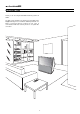
1 INSTALLATION
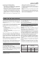
The RTX system of SIM2 comprises the elements listed below
(Fig.1):
• the Display
• the DigiOptical Image Processor
• the remote control
• the DigiOptical Image Processor power supply
• three power cables for the Display
• three power cables for the DigiOptical Image Processor
• the cable with three optical fibres for the connection between
the DigiOptical Image Processor and the Display
• 4 1.5 V AAA-type batteries for the remote control
• the use and installation manual
If some of the accessories are missing, contact your dealer as
soon as possible.
supply.
Connect the cable of the power supply to the POWER input
located on the rear panel (Fig. 4).
Only use the power supply provided with the system or a power
supply approved by SIM2.
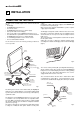
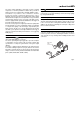
The Display is designed to stand on the floor. Place it on a level,
flat surface so that it has sufficient space for ventilation and, to
avoid reflections, do not expose it to direct sunlight or intense
light sources.
The connection to the electrical grid is located on the rear panel,
like the power switch.
Adjust the rear feet to obtain the optimum viewing angle,
according to the distance and height you sit in front of the Display
(Fig. 2).
Fig. 1
The remote control provided (IR, operating with infrared rays),
allows complete control of the system. It is only for the DigiOptical
Image Processor and the Display and can be used by pointing
at either of the two units without distinction, since each is
equipped with an IR receiver on its front.
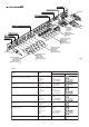
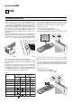
The connection between the two units is made with a cable
containing three optical fibres, each terminating in an LC
connector. The standard cable length (20 m, 65.6 ft), is sufficient
Fig. 2
Cavo
Fibra
Ferrula
Connettore
Tap po di
protezione
Punto di
sfiocco
Protection plug
Unravelling point
Unravelling poi
Cable
Connector
Fibre
Fig. 3