
Video Projector User and Installation Manual

SVD 800 HD
19
ENGLISHENGLISH
ENGLISHENGLISH
ENGLISH
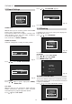
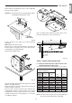
Turn the projector upside down and hang on the ceiling
with the assembly brackets
Tilt the projector to centre the vertical picture and screw
the two securing screws (H)
Note: Insert the special curved washers between the
ceiling bracket and the securing screws. For a correct
installation the concave surface of the washer should be
towards the bracket. For safety purposes, use only the
assembly kit supplied.
Fix the bracket, included in the pack, to the ceiling with
the four screws supplied.
Attention:
The bracket must be fixed properly and be
absolutely parallel with the screen
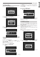
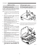
Put the projector on a table in the vertical position
(sideways)
N.B.: Take the two front feet off.
Remove the 2 screws and their washers, insert the left
bracket and fix it, using the same screws and washers,
as illustrated in the following figure.
Repeat for the right bracket.
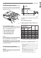
Fig. 46
SCREEN
FRONT
440
93
=
=
OBSERVE
PARALLELISM
BRACKET
Fig. 47
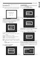
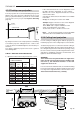
Note: the tilting angle between the base plane of the
projector and the lenses’ axis should be 14°.
Fig. 48
E
D
14°
SCREEN CENTRE
SCREEN
WALL
Fig. 49
TABLE 3: CEILING FRONT PROJECTION.
D = Distance between the line of the first hole of the
assembly bracket and the screen.
E = Distance between the ceiling and the screen centre.
SCREEN SIZE D E
USEFUL AREA 4/3
Diagonal Width Height
(Inches) (cm.) (cm.) (cm.) (cm.)
60” 121.9 91.4 204 81
80” 162.5 121.9 258 95
90” 182.9 137.2 284 104
100” 203.2 152.4 312 109
120” 243.8 182.9 366 125
150” 304.8 228.6 447 146
180” 365.7 274.3 528 167
200” 406.4 304.8 582 181
250” 508.0 381.0 718 217
300” 609.6 457.2 853 251
H
FRONT
Note:
For 16/9 screen formats, measure the width and
refer to the nearest width value in the table.