
Owner's manual


ST50GF / ST42GF
05
MAX
600 ms
Units
MAX
100 ms
Units
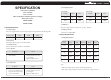
2-6. Total Output Power
SST-SG50GF SST-ST42GF
2-7. Remote ON/OFF Control
The power supply outputs shall be enabled with an active-low TTL signal.
When TTL signal is low, the DC outputs are to be enabled.
When TTL signal is high or open circuited, the DC outputs are to be disabled.
Electronic means or a mechanical switch may activate the TTL signal.
After the TTL signal is active high, must wait for 3 seconds before active low again.
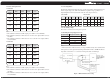
2-8. Power Sequence
FIGURE 2. Power Sequence
2-9. Power On Time (T1)
2-10. Rise Time (T2)
MAX
500 Watts
Units MAX
420 Watts
Units
2-11. Power Good Delay Time (T3)
The test environment is 25 C condition @ nominal input. see1-1
2-12. Power Good Rise Time (T4)
2-13. Hold Up Time (T5)
The test environment is 25 C & full load condition @ nominal input.
2-14. Power Fail Signal (T6)
Power good signal shall go to a down level 1ms before +5V output voltage falls below the
regulation limits during PS-ON signal pull high.
2-15.Lnitial Delay Time
3. Protections
3-1. Over Voltage Protection
When the DC outputs (+5V, +12V, +3.3V) have over voltage condition, the power supply shall
provide latch mode over voltage protection.
06
MIN
1ms
Units
MAX
1000 ms
Units
DC output
+12V
+5V
+3.3V
16.0
7.0
4.5
V
V
V
Max Unit
MAX
100 ms
Units
MIN
16 ms
Units
MIN
100 500
MAX
ms
Units
O
O