SST-ST30SF The reference SFX power supply Support standard SFX form factor and ATX via included bracket 300W continuous power output at 50℃ operating temperature rated for 24/7 operation 80 PLUS Bronze level efficiency (82%~85% efficiency at 20%~100% loading) Class-leading single +12V rail with 22A Intelligent semi-fanless operation Silent running 80mm fan with 18dBA minimum Single PCI-E 6pin connectors support Active PFC
SFX Form Factor SST-ST30SF 300W Switching Power Supply Active PFC Circuit Full Range Input 1. GENERAL DESCRIPTION AND SCOPE This is the specification of Model SST-ST30SF; AC-line powered switching power supply with active PFC (Power Factor Correction) circuit, meet EN61000-3-2. Also, 5Vsb power is less than 0.5Winput at power off mode (PS_ON input at high state) which is comply with ErP Lot 6 year 2013 requirement.
2.2. SAFETY CB: IEC 60950~1:2005(2nd Edition) and/or EN 60950~1:2006 +A11:2009 UL: UL 60951-1 , 2nd Edition, 2007-03-27 TUV: EN 60950-1:2006+All 3. INPUT ELECTRICAL SPECIFICATIONS 3.1. AC INPUT Parameter (1) Mi n. Nom. Max. Unit Vin (115VAC) 90 115 132 VAC rms Vin (230VAC) 180 230 264 VAC rms Vin Frequency 47 -- 63 HZ ◆ Nominal voltages for test purposes are considered to be within ±1.0V of nominal. 3.2.
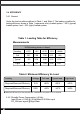
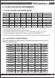
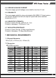
3.4. EFFICIENCY 3.4.1 General Under the load conditions defined in Table 1. and Table 2. The loading condition for testing efficiency shown in Table 1 represents a fully loaded system. ~ 50% (typical) loaded system. and ~ 20% (light) loaded system. Table 1. Loading Table for Efficiency Measurements 300W(loading shown in Amps) Loading +12V +5V +3.3V -12V +5Vsb Full 18.7 7.58 7.96 0.31 1.56 Typical 9.3 3.79 3.98 0.16 0.78 Light 3.7 1.52 1.59 0.06 0.31 Table 2.
4 . OUTPUT ELECTRICAL REQUIREMENTS 4.1. OUTPUT VOLTAGE AND CURRENT RATING Output MINIMUM NORMAL MAXIMUM PEAK LOAD LINE LOAD LOAD LOAD LOAD REG REG RIPPLE & NOISE +3.3V 0.1A 10.5A 21A ±5% ±1% 50mV P-P +5V 0.2A 10A 20A ±5% ±1% 50mV P-P +12V 0.5A 8A 22A ±5% ±1% 120mV P-P -12V 0A 0.25A 0.5A ±10% ±1% 120mV P-P +5VSB 0A 1.25A 2.5A ±5% ±1% 50mV P-P 3A ( 1 ) +3.3V & 5V total output not exceed 103W. ( 2 ) Total output continuous shall not exceed 300W watts.
4.3. HOLD-UP TIME (@Typical load of Table 1.) 115V / 60Hz : 17 m sec. minimum. 230V / 50Hz : 17 m sec. minimum. The output voltage will remain within specification, in the event that the input power is removed or interrupted, for the duration of one cycle of the input frequency. The interruption may occur at any point in the AC voltage cycle. The power good signal shall remain high during this test. 4.4. OUTPUT RISE TIME (10% TO 95% OF FINAL OUTPUT VALUE, @FULL LOAD) 115V-rms or 230V-rms + 3.
4.7. SHORT CIRCUIT PROTECTION Output short circuit is defined to be a short circuit load of less than 0.1 ohm. In the event of an output short circuit condition on +3.3V, +5V, +12V or –12V output, the power supply will shutdown and latch off without damage to the power supply.The power supply shall return to normal operation after the short circuit has been removed and the power switch has been turned off for no more than 2 seconds. 4.8. POWER SIGNAL POWER GOOD @115/230V,FULL LOAD 100 –500m sec.
4.9. The main power supply shall be off when the PS_ON pin is floating (open collector). The ON/STBY pin of P1 must remain off state for 5 Sec (maximum) prior to switching to the ON state 5. FAN NOISE REQUIREMENTS 5.1.The subject power supply is cooled by a self-contained, 80mm×15mm, 12VDC fan. 6. ENVIRONMENTAL REQUIREMENTS The power supply will be compliant with each item in this specification for the following Environmental conditions. 6.1. TEMPERATURE RANGE Operating +10 to +50 deg.
6.4. GROUND LEAKAGE CURRENT The power supply ground leakage current shall be less than 3.5 mA. 6.5. RELIABILITY The power supply reliability, when calculated by MIL-HDBK-217;latest revision, are exceed 100,000 hours with all output at Typical load and an ambient temperature of 25℃. 6.6. DIELECTRIC STRENGTH Primary to Frame Ground : 1800 Vac for 1 sec. Primary to Secondary : 1800Vac for 1 sec 6.7. INSULATION RESISTANCE Primary to Frame Ground : 20 Meg.ohms Minimum Primary to Secondary : 20 Meg.
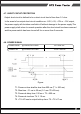
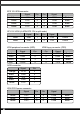
EPS 12V 8PIN connector Yellow Yellow Yellow Yellow Signal Pin Pin Signal +12V +12V +12V +12V 5 6 7 8 1 2 3 4 COM COM COM COM Black Black Black Black ATX 12V 4PIN (4+4PIN EPS 12V in split mode) Signal GND GND Black Black Pin 1 2 4PIN peripheral connector (HDD) Signal +12V +12V Yellow Yellow 4PIN floppy connector (FDD) Signal +12V COM COM +5VDC Pin 1 2 3 4 SATA connector Signal Orange +3.
Warranty Information Warranty terms & conditions 1.Product component defects or damages resulted from defective production is covered under warranty. Defects or damages with the following conditions will be fixed or replaced under SilverStone Technology’s jurisdiction. a)Usage in accordance with instructions provided in this manual, with no misuse, overuse, or other inappropriate actions.
April, 2013 G11219230