
manual


ST65F-G / ST55F-G
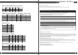
2.3 Output Ripple
2.3.1 Ripple regulation
2.3.2 Definition
The ripple voltage of the outputs shall be measured at the pins of the output connector
when terminated in the load impedance specified in figure 1. Ripple and noise are
measured at the connectors with a 0.1uF ceramic capacitor and a 10uF electrolytic
capacitor to simulate system loading. Ripple shall be measured under any condition of
line voltage, output load, line frequency, operation temperature.
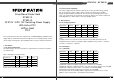
1.Maximum continuous total DC output power should not exceed 650W.
2.Maximum continuous combined load on +3.3V and +5V outputs shall not exceed 150W.
3.Maximum combined current for the +12V outputs shall be 54A(648W).
4.Maximum peak total DC output power should not exceed 700W.
5.Peak power and current loading shall be supported for a minimum of 12 second.
6.When +12V is load to 25A , -12V minimum load is 0.02A.
2.2.2: (ST65F-G)
Parameter
+3.3V
+5V
+12V
-12V
+5VSB
Min
0.2
0.2
0.3
0
0
Nom.
-
-
-
-
-
Max
22
20
54
0.3
2.5
Peak
57
3.5
Unit
Amps
Amps
Amps
Amps
Amps
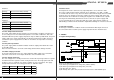
Parameter
+3.3V
+5V
+12V1
+12V2
-12V
+5VSB
Ripple&Noise
50
50
120
120
100
50
Unit
mVp-p
mVp-p
mVp-p
mVp-p
mVp-p
mVp-p
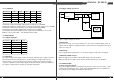
2.3.3 Ripple voltage test circuit
2.4 Overshoot
Any overshoot at turn on or turn off shall be less 10% of the norminal voltage value, all
outputs shall be within the regulation limit of section 2.0 before issuing the power good
signal of section 5.0.
2.5 Efficiency
Power supply efficiency typical 87% for at normal voltage at full load on all outputs.
2.6 Remote ON/OFF control
When the logic level "PS-ON" is low, the DC outputs are to be enabled.
When the logic level is high or open collector, the DC outputs are to be disabled.
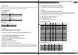
3.1 Over current protection
The power supply shall have current limit to prevent the +3.3V, +5V, and +12V1, +12V2
outputs from exceeding the values shown in the following Table.If the current limits are
exceeded the power supply shall shutdown and latch off.
AC Hot
AC Neutral
Power Supply
V out
V return
10uF 0.1uF
Load
Scope
AC Ground
Figure 1. Ripple voltage test circuit
3.0 PROTECTION