
User's Manual

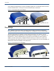
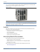
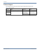
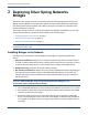
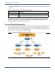
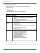
Table Of Contents
- Bridges Hardware Guide
- Contents
- 1 Introduction
- 2 Deploying Silver Spring Networks Bridges
- A Specifications
- Overview
- eBridge and sBridge Features
- Silver Spring Networks eBridge Specifications
- Silver Spring Networks sBridge Specifications
- Regulatory Compliance - Module Certifications
- FCC Certification (Radiated/Conducted Emissions Compliance FCC Part 15.247)
- Industry Canada Certification (Radiated/Conducted Emissions Compliance RSS-210)
- C-Tick Level 3 (Radiated/Conducted Emissions Compliance AS/NZS4268, AS/NZS4778)
- Silver Spring Networks NIC, FCC IDs: OWS-NIC515 IC: 5975A-NIC515 (sBridge) OWS-NIC506, IC:5875A-NIC506 (eBridge)
- Glossary
- Index

Bridges Hardware Guide Silver Spring Networks 8
2 Deploying Silver Spring Networks Bridges
2 Deploying Silver Spring Networks
Bridges
Essential to the complete creation of a DA network are the Silver Spring primary devices: the
eBridge and the sBridge. The DA network is designed to help utilities effectively communicate
with field-installed remote terminal units (RTUs) and power system device controllers in the
electrical distribution network.
This chapter introduces the use of Silver Spring Networks eBridges and sBridges to create and
support the Distribution Automation (DA) network, in the following topics:
• Installing Bridges in the Network on page 8
• Deployment Considerations on page 10
• Deployment Mode Examples on page 14
Note: For complete information on configuring and deploying bridges, please see the Bridge
Configurator 2.0 User’s Guide.
Installing Bridges in the Network
Four basic steps are required to install eBridges and sBridges for supporting Distribution
devices:
1. Physical Installation: bridges are not weather-hardened. They must be installed indoors
or inside a weather-hardened enclosure, normally in the same enclosure as the RTU or device
controller. Four mounting holes are located on the bottom edges of the bridge chassis.
2. Bridge Powerup: preferably, along with a battery backup.
3. RF Antenna Attachment: bridges may be connected with different antennas depending on
the application. All antennas connect to the SMA female RF connector on the back of all
bridges. Keep the following considerations in mind when attaching the proper antenna for
the current device:
CAUTION: With the sBridge, using an antenna with greater than 3dBi gain is not
allowed. Up to 6dBi is allowable with the eBridge.
a. The recommended antennas for use in outdoor environments are listed in Table 2, below.
b. An N-Female to SMA-male adapter is required for antenna cable connection to the SMA
connector on the back of the bridge.
c. Because the SMA connector is so small, physical stress may result when connecting a
heavy coaxial transmission cable to the back of the eBridge or sBridge during installation.
Use a pigtail on the SMA connector to support the weight of a heavy transmission line to
the bridge.