
User's Manual
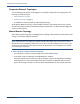
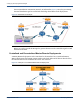
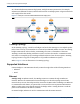
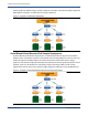
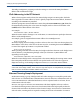
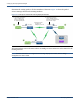
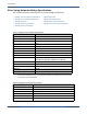
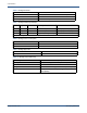
Table Of Contents
- Bridges Hardware Guide
- Contents
- 1 Introduction
- 2 Deploying Silver Spring Networks Bridges
- A Specifications
- Overview
- eBridge and sBridge Features
- Silver Spring Networks eBridge Specifications
- Silver Spring Networks sBridge Specifications
- Regulatory Compliance - Module Certifications
- FCC Certification (Radiated/Conducted Emissions Compliance FCC Part 15.247)
- Industry Canada Certification (Radiated/Conducted Emissions Compliance RSS-210)
- C-Tick Level 3 (Radiated/Conducted Emissions Compliance AS/NZS4268, AS/NZS4778)
- Silver Spring Networks NIC, FCC IDs: OWS-NIC515 IC: 5975A-NIC515 (sBridge) OWS-NIC506, IC:5875A-NIC506 (eBridge)
- Glossary
- Index

Bridges Hardware Guide Silver Spring Networks 14
2 Deploying Silver Spring Networks Bridges
Serial
In serial mode, the remote or teaming bridge connects to an RTU through a serial interface.
Because serial RTUs have DNP addresses, the end point of the IP network is the bridge device.
Note: The Silver Spring Networks sBridge provides two DB-9 serial interfaces. (The eBridge provides
a single DB-9 serial port.) On the sBridge, one port is dedicated to DNP3 traffic for the RTU (Serial Port
2) and the second serial port (Serial Port 1) passes raw serial traffic regardless of protocol, operating
as a terminal communication port for remote troubleshooting and control. Either port can function with
either setting; use the Bridge Configurator software to configure the ports.
When the remote or teaming bridge receives a packet, it removes the IP header and forwards the
DNP3 payload serially to the RTU device.
During network configuration, a DNP3-to-IP mapping table is created by the Bridge Configurator
software; this mapping table is stored on the master bridge. When the master bridge receives a
DNP3 packet from the SCADA system, it uses that table to look up the destination IP address,
encapsulates the DNP3 packet into an IP header and sends it to the destination bridge, where it is
de-encapsulated back into DNP3 and forwarded over the serial port to the destination RTU.
The RTUs communicate with the master bridge using the master bridge’s IP address. The
eBridge and sBridge support both IPv4 and IPv6 in serial mode.
Deployment Mode Examples
This section provides the following deployment mode examples:
• Mixed IPv4 Sample Deployment (Master eBridge only) below
• Serial Master/Serial Remote IPv6 Sample Deployment on page 15
• Ethernet Teaming Sample Deployment on page 16
Mixed IPv4 Sample Deployment (Master eBridge only)
In Mixed deployments, the master bridge connects to the SCADA master through its Ethernet
interface, while its associated remote bridges connect to RTUs, in this case voltage regulators
shown in Figure 8, through serial ports. The master bridge acts as a router, routing packets
between its Ethernet and RF interfaces, and does not perform DNP encapsulation. The remotes
encapsulate DNP messages coming from the voltage regulators into IP messages, and pass them
on to the master bridge. The remote bridges also de-encapsulate incoming IP messages from the