
User's Manual
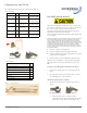

Gas IMU Quick Install
circle fits around the notch on the meter, as
shown:
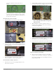
On a Rockwell meter, attach the magnet assembly
so that the protrusion holding the magnet points
down and to the left and the inner pin is inserted
into the index screw hole.
Attach the meter index to the IMU:
1. Align the IMU drive train with the index wriggler.
2. Use the two index screws to firmly attach the index to
the IMU. (Torque: 13-15 in. lbs. for Rockwell; 14-17 in.
lbs. for American.)
3. Rotate the IMU drive train two turns, clockwise or
counter-clockwise to ensure it spins freely.
Attach the IMU assembly to the meter:
1. Insert the four cover screws through the index cover
and set the cover down.
2. Attach the IMU assembly to the meter so that the drive
train aligns with the meter wriggler and the screw holes
on the meter align with those on the cover.
Note: The photo above shows two types of
IMU drive train.
3. While holding the enclosure against the meter to
maintain proper alignment, rotate the test hand to
verify proper engagement.
4. Attach the index cover and screws to the meter.
5. Tighten the four screws firmly. (Torque: 17-20 in. lbs.
for Rockwell; 25-35 in. lbs. for American.)
6. Use the nut driver to push the two red tamper seals into
place.
Prepare the IMU for programming:
z Swipe the service magnet over the top of the IMU.
Doing so wakes up the IMU, enabling you to program it.
Refer to the documentation and training material for
programming the IMU.