
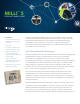
User's Manual
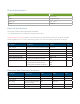
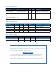
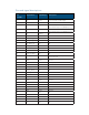
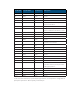

Pin Number Signal Name
Input/Output
Description
33 NC N/A NC
34 GND Power Ground
35 NC N/A NC
36 NC N/A NC
37 GPIO_5 I/O Interrupt pin – Pin to wake up host
processor from Milli 5
38 NC N/A NC
39 GPIO_8 Output Is an open collector pin that Milli 5 would
pull low to affect the host device to reset.
40 GND Power Ground
41 NC N/A NC
42 GPIO_6 I/O NC
43 GND Power Ground
44 GPIO_7 Input Interrupt pin - wakes up Milli 5 so host
processor can send data
45 NC N/A NC
46 GND Power Ground
47 NC N/A NC
48 NC N/A NC
49 GND Power Ground
50 NC N/A NC
51 NC N/A NC
52 NC N/A NC
53 RSET_N Input Milli 5 module master reset. Active low
input. When asserted, all outputs will be
made high impedance
54 GND Power Ground
55 NC N/A NC
56 3V3 Power 3.1V – 3.6V main module supply
57-72 GND Power Ground
* Pins 3‑16 are bi‑directional, inputs are pull up/pull down, and outputs are congurable as
push‑pull or open drain. Drive capacity varies with pin.