Gas IMU Installation and Configuration 2009 innovation in utility networking
Overview • Remove existing index and prepare the meter • Attach the tamper magnet holder • Attach the index to the IMU • Attach the IMU assembly to the meter • Prepare IMU for programming © 2010 Silver Spring Networks | Company Confidential 2
Safety First! • Always follow applicable standards for safety! • Refer to the meter documentation for further safety information. • Follow your employer’s best practices. • If you smell gas, report it to the utility.
RF Exposure Notice (509) • The antenna of this transmitter must not be co-located or operating in conjunction with any other antenna or transmitter. • The device should be installed so that people will not come within 20 cm (8 in.) of the antenna. • This equipment has been tested and found to comply with Part 15 of the FCC Rules, and with Industry Canada licence-exempt RSS standard(s).
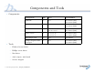
Components and Tools • Components: • Tools: Component Qty.
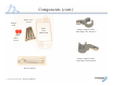
Components (cont.
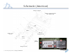
Schematic (American) Tamper magnet Tamper magnet holder (for American) IMU Index Battery compartment Index cover screws Index cover Index screws Tamper seals © 2010 Silver Spring Networks | Company Confidential 7
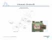
Schematic (Rockwell) Tamper magnet holder and magnet (for Rockwell) IMU Battery compartment Index cover screws Index Index cover Index screws Tamper seals © 2010 Silver Spring Networks | Company Confidential 8
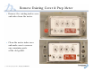
Remove Existing Cover & Prep Meter • Remove the existing index cover and index from the meter. • Clean the meter index area and make sure to remove any remaining parts of the old gasket.
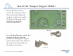
Attach the Tamper Magnet Holder • On an American meter, attach the magnet so that the protrusion holding the magnet points down and to the left and the gap in the circle fits around the notch on the meter. American • On a Rockwell meter, attach the magnet holder so that the protrusion holding the magnet points down and to the left and the inner pin is inserted into the index screw hole.
Attach Meter Index to IMU • Align the IMU drive train with the index wriggler.
Attach Meter Index to IMU (cont.) • Use the two index screws to firmly attach the index to the IMU. • Torque: – Rockwell: 13-15 inch pounds – American: 14-17 inch pounds • Rotate the IMU drive train two turns, clockwise or counter-clockwise to ensure it spins freely.
Attach IMU Assembly to Meter • Insert the four cover screws through the index cover and set the cover down. • Attach the IMU assembly to the meter so that the drive train aligns with the meter wriggler and the screw holes on the meter align with those on the cover.
Attach IMU Assembly to Meter (cont.) • While holding the enclosure against the meter to maintain proper alignment, rotate the test hand to verify proper engagement. • Attach the index cover and screws to the meter. • Torque: – Rockwell: 17-20 inch pounds – American: 25-35 inch pounds • Tighten the four screws firmly. • Use the nut driver to push the two red tamper seals into place.
Prepare the IMU for Programming • Slowly pass the service magnet once (for 2 to 5 seconds) over the top of the IMU. • Doing so wakes up the IMU, enabling you to program it.
Rockwell 415 Gas IMU Installation and Configuration August 2010 innovation in utility networking
Rockwell 415 IMU Retrofit Overview • Check the components and tools list. • Remove the index cover and index. • Fasten the adapter plate to the meter. • Fasten the meter index to the IMU. • Fasten the IMU to the meter. • Fasten the index lens cover and the tamper seal. • Prepare the IMU for programming.
Check the Components and Tools List • Components: Component Qty. Size Part Numbers Silver Spring Networks IMU 1 n/a 178-000101 rev 06 Adapter system 1 n/a 178-000098 rev 02 Index cover 1 n/a 976-000196 rev 1 Index cover screws 4 10-24 X 2.
Check the Components and Tools List (continued) IMU Index cover Tamper seals Index screws Index cover screws Adapter plate Service magnet © 2010 Silver Spring Networks | Company Confidential 19
Check the components and tools list (continued) Rockwell 415 schematic © 2010 Silver Spring Networks | Company Confidential 20
Remove the Index Cover and Index 1. Remove the existing index cover and index from the meter. 2. Clean the meter index area and make sure to remove any remaining parts of the old gasket.
Fasten the Adapter Plate to the Meter 1. Position the adapter plate pin into the center left hole on the meter and seat the adapter onto the meter. 2. Position an index screw in the center right hole and fasten the adapter using 7-8 in-lbs of torque.
Fasten the Adapter Plate to the Meter (continued) 4. Rotate the gear on the plate clockwise until you feel it engage with the gear inside the IMU. Make sure that the gears are not locked up.
Fasten the Meter Index to the IMU 1. Attach the meter index to the IMU with two index screws using 7-8 in-lbs of torque. 2. Make sure that the gears engage by moving the lower dial.
Fasten the IMU to the meter 1. Angling in from the left, seat the IMU on the adapter plate on the meter. Adjust the rear gasket as needed and make sure that the gears are engaged but not locked up. 2. Rotate the lower dial to make sure it is engaged with the gear on the adapter.
Fasten the index lens cover and the tamper seals 1. Fasten the lens cover and the IMU to the meter using the four long lens cover screws and a torque of 13-15 in-lbs. 2. Use a nut driver to push the three tamper seals into the openings on the IMU.
Prepare the IMU for Programming Slowly pass the service magnet once (for 2 to 5 seconds) over the top of the IMU. This activates the IMU so you can program it.