
User Instructions

Document Type: Test Procedure
Equipment Name: Innovatec C and I Electric
Author: Dithien V. Ho, RF Design Engineer.
Page 7 of 24
3. PCA Sub-Assembly RF Communications Test
3.1. System Hardware Set-up:
3.1.1.
Firmware Installation:
Remove AC line voltage from PCA power leads.
Disconnect battery lead from Charger Assembly.
Verify installation of the EPROM with appropriate firmware reversion.
3.1.2.
NCI Installation:
Install the NCI with version 2 communications IC (Siliconians) onto the PCA with appropriate
antenna, 900 MHz, and 50 Ohms impedance.
3.1.3.
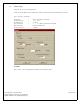
Electric Meter RS-232 Communication connection:
Install the Electric Meter to connector J7 as follow:
J7, Pin 12 = Transmit (Pin 2 of the DB9 Meter communications cable)
J7, Pin 11 = Receive (Pin 3 of the DB9 Meter communications cable)
J7, Pin 10 = Ground (Pin 5 of the DB9 Meter communications cable)
Power up the electric meter.
3.1.4.
Power on test:
Apply 120V AC line voltage to the PCA power leads, observe for the Status Indicator LEDs, make
sure the Green and Yellow LEDs are illuminated.
Reconnect battery lead to Charger Assembly.
Pass__Fail___