
User Instructions

Document Type: Test Procedure
Equipment Name: Innovatec C and I Electric
Author: Dithien V. Ho, RF Design Engineer.
Page 5 of 24
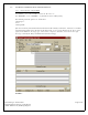
2.3. Power Supply Test
2.3.1. Connect 220 V variac (with isolation transformer and built-in fuse) to the input connector of
power supply. Then, slowly bring up the voltage from 0 –85V while monitoring the line current.
The line current at 85V should be < 15 mA
Pass____Fail___
2.3.2. Wait few seconds and then verify all LEDs are turned on.
Pass____Fail___
2.3.3. Measure the DC voltage between pins 3 and 21 of NCI connector (J7).
Specification: 5.5 – 5.7V DC.
Pass____Fail___
2.3.4. Measure DC voltage between pins 15 and 21 of NCI connector (J7).
Specification: 5.0 to 5.1 Vdc
Pass____Fail___
2.3.5. Measure DC voltage between pins 17 and 21 of NCI connector (J7).
Specification: 3.5 to 3.7 Vdc
Pass____Fail___
2.3.6. Measure DC voltage between pins 2 and 5 of Molex connector (JP2).
Specification: 12 to 14 Vdc
Pass____Fail___
2.3.7. Disconnect AC Power to UUT and install NCI unit onto the main board. Then, bring the voltage
slowly up to 85 Vac and repeat the above steps 4.2- 4.6.
Pass____Fail___
2.3.8. Bring up the AC line voltage slowly from 85 to 265 Vac and repeat the above steps with NCI
installed (full-load).
Pass____Fail___