
User's Manual

3
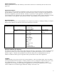
Open Issues
What type of location information will we use (e.g., lat, long, elevation, pole #) for gateways, relays and meters?
What tool will we adopt for network RF planning, and how will we interface the rest of the system to it?
Introduction
The Enterprise Network and Internet Communications (ENICS) system is a set of software applications that allow
either utilities or Innovatec acting as a service bureau to manage and operate an Innovatec communications network.
The functions required include the ability to read meters, monitor network operation, install, decommission, swap and
test all elements in the communications network and handle alarms. In addition, Innovatec must have a means of
planning and laying out communications networks, training users and demonstrating the system to prospective
customers. For development it is desirable to have some means of exercising the communications network in a more
intensive manner than we have been able to in the past. It will be necessary to update and possibly gather data from
databases that are not part of the Innovatec system. For example, a utility may have a billing database (and
applications that use it) already in place. Data from scheduled reads might be placed into this billing database.
Finally, it should be possible to log events of interest for later analysis either by utility personnel or applications in the
Innovatec system. Innovatec plans to eventually use the system for very large installations (on the order of 10 million
meters or more). Thus, it is necessary to architect and build the system in such a way that its functions can be
distributed across multiple machines and possibly multiple servers. In addition, in Innovatec’s role as a service
bureau, it may be necessary to site a gateway server and possibly some server functions at a customer site, while the
rest are handled at Innovatec’s offices. For example, a utility may want to put modems at their site so that calls to
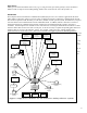
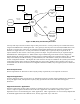
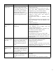
gateways are local calls, while Innovatec administers the network remotely. A high level schematic for the Innovatec
utility system is shown in Figure 1. In the schematic, each of the applications is shown as if it was a traditional
monolithic program. However, the Innovatec system is being designed and implemented as a multitier architecture in
which the user interface is a set of Java applets and HTML pages which use a set of servants to access various
services, such as database access. This document supplies a general organization and partitioning for the system as
well as requirements that apply to all applications. The requirements for the various components of the system are
contained in their own requirements documents.
Network Configuration
Database
SW/HW Compatability
Database
Network Planning
Database
Alarm Configuration
Database
Logging
Database
Billing
Database
(Legacy)
Utility Physical
Assets Database
(Legacy)
Gateway
Server
Innovatec
Utility
Server
Production
Network
Network
Emulator
Network
Testbed
Field Service
Application
(Interactive)
Network
Configuration
Manager
(Interactive)
Alarm Configuration
Manager
(Interactive)
Field Service
Database
Field Service
Laptop or Handheld
via direct TCP/ IP or
d i al up PPP
Network Planning
and Layout
converter
Billing Application
(Legacy)
Physical Assets
Tracking
(Legacy)
Meter
Reader
(Interactive)
Network
Exerciser
(Autonomous)
Network Health
Monitor
(Autonomous)
Alarm Receiver
(Autonomous)
Figure 1: High level schematic for the Innovatec utility software system