
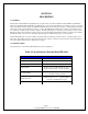
Specifications


Page 8
Copyright 2006 Robert A. Larson, KC9ICH
4-18 Reset
4-19 At the end of the 9 millisecond display period, the display is blanked. Counters A9, A10 and A15 are reset by timing
signal A inverted and counters A7 and A8 are both preset to 5 by A completing the sample, display, reset sequence which is
then repeated.
4-20 Power Supply
4-21 The power supply operates from either 117VAC or 13.8VDC. Though no damage would occur if the unit was connected
to both sources simultaneously, no assurances could be given for which source was supplying power at any particular time.
117VAC is connected to T1 through S1 and F2. 9VAC, nominal, at the output of T1, is converted to 12.0 VDC by the bridge
rectifier. 12.6VDC powers the display which is filtered by C4 and regulated to 5VDC by the F74MO5UC regulator. C5, C6,
and C7 provide RF bypassing.
4-22 13.8VDC enters through CR1, S1, F1, and CR2, CR3, and CR4. The diodes drop the input by approximately 3.5 volts to
approximately 10.3 volts which is then applied to the displays and to the 5 V regulator.