
Specifications
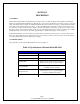


Page 7
Copyright 2006 Robert A. Larson, KC9ICH
4-12 Timing Signal Generation
4-13 The identifications of the timing signals of Figure 4-2 are derived from the IC and terminals of their origins. For
example, the 500 Hz clock originates from A12, terminal 11. It is identified as A12-11. Timing signal A, which is the reset
pulse, is generated by firs combining the 500 Hz clock with A11-11 in NAND gate A6-A. Referring to Figure 4-2 it is seen
that the inputs to A6-A are both high only during the time of each 5th successive clock pulse. This produces a train of 1
millisecond negative pulses at 1/5th the clock rate. This pulse train is then inverted in Al-A and applied to the input of NAND
gate A6-D along with a 50 Hz square wave from Al-B which is waveform C inverted. The inputs to A6-D are both high only
during each second pulse of A1-A-2. This eliminates the intervening pulse and generates waveform A. Waveform B is
generated by combining waveform A and the inverted waveform C, (Al-B-4), in NAND gate A6-C. Waveform A goes low
for 1 millisecond prior to A1-B-4. This then generates a pulse that is high for 11 milliseconds and low for 9 milliseconds and
which is inverted for waveform B.
4-14 Signal Sampling
4-15 The VFO signal from the 1011D is applied to the base of Q1 which uses negative feedback and a tuned circuit in series
with the collector to provide an essentially flat response across the frequency range of the VFO. The output of the amplifier is
then applied to the sampling gate, A6-B. A6-B is enabled by timing signal C for 10 milliseconds out of the 20 millisecond
time base. The VFO frequency is, thus, gated to the counter chain for that period. The gated VFO signal is first prescaled by
10 in A15. A10 is a decade counter and its terminals 12, 9, 8 and 11, respectively, will produce a BCD code equal to the
number of pulses appearing at its clock input terminal 14. Since it is a decade counter, terminal 11, the ―8‖ output, will be
high during the eighth and ninth clock pulses. On the tenth pulse, it will go low clocking A9 which is another decade counter.
(The 7490 is clocked on the negative going edge of the input pulse). After ten input pulses, the BCD code at the output
terminals of A10 will be ―0‖ and at the output of A12 it will be ―1‖. A8 will be clocked by A9 when A9 accumulates 10
counts after 100 input pulses to A10. A7 will similarly be clocked by A8 after 1000 input pulses to A10. At the end of 10
milliseconds, when the sampling gate is disabled, the four counters will contain numbers in BCD code proportional to the
VFO frequency ÷5.5 KHz. A8 and A7 were each preset prior to the sampling period, to a count of 5. If the receiver is tuned
to 28.000 MHz the input frequency to the FD-1011 will be 22.500 MHz. Since the gate is opened for only 10 milliseconds,
the number of input pulses to A15 will be 225,000 which will he divided to 22,500 prior to the input of A10. This will be
divided in A10, A9, A8 and A7 as previously discussed. The most significant figure will overflow out of A7 and will be lost.
(Since it is always a ―2‖, this is of no importance as the most significant number in the display is permanently set at ―2‖).
Since A7 and A8 will both preset to 5, they will now have been clocked to 8 and 0 respectively by the next two significant
numbers: e.g., 25 + 55 equals 80. (Remember, the first 2 overflowed). A9 and A10 both contain BCD codes of ―0‖. The
numbers in the counters, reading from right to left are 8-0-0-0.
4-16 Display
4-17 Immediately on disabling of the sample gate, timing signal B unblanks decoder drivers A2, A3, A4 and A5 for 9
milliseconds. The decoder drivers convert the BCD code to a code that will display the BCD number on the seven-segment
displays Z1, Z2, Z3 and Z4, to which they are connected. A fifth seven - segment display, Z5, is connected so as to always
display a number 2 and the decimal point in Z4 is permanently connected. The display now reads 28.000 MHz. The 1011D
VFO oscillator operates low side, 5.5 MHz below the frequency to which the transceiver is tuned. If we add 5.5 MHz to the
VFO frequency of 22.500 MHz the sum is 28.000 MHz. This is the frequency to which the transceiver is tuned. The resistors
that interconnect the decoder drivers and the display limit the current through the display segments to approximately 15
milliamps per segment.