
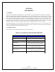
Specifications


Page 6
Copyright 2006 Robert A. Larson, KC9ICH
SECTION IV
THEORY OF OPERATION
4-1 GENERAL
4-2 This section of the manual describes, in detail, the operation of the amplifiers and logic circuits of the Siltronix FD-1011
Digital Dial. The descriptions are in two parts. The first, supported by the block diagram of Figure 4-1, describes the circuit
functionally as a prelude to the more detailed descriptions of the second part which is supported by the logic/schematic
diagram of Figure 5-2 and a timing diagram, Figure 4-2. The descriptions herein assume knowledge on the part of the
technician of the operation of digital logic circuits such as NAND gates, inverters, counters, decoder/drivers and seven-
segment display devices. The FD-1011 uses many integrated circuit packages that contain a multiplicity of identical circuits.
The circuits within these packages are not discussed in this text. Only the responses of certain outputs which are relative to
the discussion of the FD-1011 are detailed. Manufacturer‘s published data, and other publications readily available to
electronics technicians, provide the details of the internal circuits of these devices.
4-3 FUNCTIONAL DESCRIPTION
4-4 Refer now to Figure 4-1. When the FD-1011 is connected to a Siltronix Model 1011D transceiver, the output of the
transceiver VFO is coupled to the input amplifier of the FD-1011. The sampling gate is enabled for 10 milliseconds by the
timing system. The VFO frequency is then divided by a factor of 10 in each of the following decade counters. When the gate
is disabled at the end of the sampling period, each of the counters that comprise the division chain will contain a discrete
number in BCD code. These numbers as a group are directly related to the input frequency. The most significant figure will
be lost and the next most significant figure, plus a count of 5, will be contained in the last counter of the chain and the least
significant figure will be in the second counter. The count of 5 that is added is part of the conversion from the VFO frequency
to the operating frequency. The operating frequency is the desired display. The addition is further explained in the detailed
circuit description.
4-5 When the sampling period ends, the decoder / drivers are enabled for 9 milliseconds. They convert the BCD codes to a
code that will drive the seven segment numerical displays. At the end of the 9 millisecond period, the display is turned off;
the counters are reset or preset as appropriate. The sequence is then repeated. During the sampling period the display is blank,
however, the pulse rate is 50 Hz and it appears to the human eye that the display is on continually.
4-6 A crystal controlled oscillator operating at 2.048 MHz is the basic timing system. This frequency is first divided by a
factor of 4096 and then further divided by 5 and then 2 to generate the signals from which the system timing signals will be
generated. The timing system, through the combination of signals applied to gates and inverters, generates the sampling,
display and reset timing signals which control the sampling, display and reset sequence.
4-7 DETAILED DESCRIPTION
4-8 Unless otherwise noted, all circuit references in this text are to the schematic / logic diagram of Figure 5-2.
4-9 System Clock
4-10 The system clock frequency stability is maintained by a crystal controlled oscillator comprised of quartz crystal V1
inverters A14-D and A14-E and associated components. The oscillator operates at a frequency of 2.048 MHz and this
frequency is adjusted within small limits by variable capacitor C18. This permits precise adjustment of the clock frequency.
4-11 The 2.048 MHz signal from the oscillator is divided by a factor of 16 in each of the counters, A12, A13, and A14 for a
total division of 4096. The frequency at the output of A12 is 500 Hz. This is further divided by 5 to produce signals A11-11
and A11-12 shown in Figure 4-2.