
Specifications

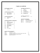


Page 4
Copyright 2006 Robert A. Larson, KC9ICH
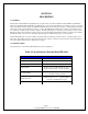
SECTION II
INSTALLATION
2-1 FIXED INSTALLATION
2-2 To install the FD-1011 as a companion unit to a Model 1011D Transceiver operating from 117VAC, insert the AC
connector from the FD-1011 into the AC receptacle on the rear of the 1011D marked ―FD-1011 ACC‖ (117VAC SW). This
receptacle is energized whenever the Model 1011D is turned on, therefore, the FD-1011 power switch may be left on with
power being controlled by the Model 1011D. Plug the miniature phone plug that is on the end of the FD-1011 coaxial cable,
into the mating miniature phone jack on the rear of the Model 1011D marked ―FD-1011 ACC‖. Connect a ground strap
between the chassis of the 1011D and the FD-1011 using the ground post and wing nut for attachment. Place the FD-1011
alongside the transceiver NEVER ON TOP OF IT.
CAUTION
Placing the FD-1011 on top of the Model 1011D Transceiver will interfere with normal convection cooling of the 1011D and
can adversely affect component life in that unit. Electrical interference may also be encountered.
2-3 MOBILE INSTALLATION
2-4 Installation of the FD-1011 in mobile applications, or wherever 13.8VDC is used to power the Model 1011 Transceiver,
requires that the 13.8VDC source be connected to the two binding posts on the rear of the FD-1011. The positive (+) lead
must be connected to the red binding post and the negative (—) lead to the black binding post. The chassis may be connected
to either the positive or negative side of the line as both binding posts are insulated from the chassis. A ground strap should
be connected between the Model 1011D Transceiver and the FD-1011 Digital Dial using the ground post and wing nut on the
FD-1011.
2-5 In mobile installations, where the two units may be separated up to the length of the interconnecting coaxial cable
furnished with the FD-1011, the two units must be grounded to each other either by a single ground strap between them or
through the vehicle structure. Do not rely on mounting structure for such grounds but use heavy conductors attached to the
binding posts. Keep ground leads as short as possible.
CAUTION
Under no circumstances should the FD-1011 be connected to the Model 1011D Transceiver through either AC receptacle on
the rear of the 1011D when the transceiver is powered from the l3.8VDC source through the Model 14A power adapter.
Damage to the FD-1011 will result.
2-6 VFO CONNECTION
2-7 Connection to the VFO output of the Model 1011D Transceiver is made with the miniature phone plug on the end of the
coaxial cable from the FD-1011 which is plugged into the matching miniature phone jack on the rear of the 1011D
Transceiver marked ―FD-1011 ACC‖.