
Specifications
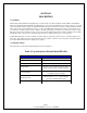


Page 10
Copyright 2006 Robert A. Larson, KC9ICH
SECTION V
MAINTENANCE
5-1 GENERAL
5-2 The Siltronix FD-1011 Digital Dial requires no periodic or preventative maintenance. Maintenance procedures, therefore,
cover calibration, disassembly and troubleshooting.
5-3 CALIBRATION
5-4 Connect a counter to the 1011D VFO output or to a signal generator and set the frequency to 23.500 MHz ± 0.0001 MHz.
Next, connect the source of that frequency to the input of the FD-1011. Use an INSULATED screwdriver and adjust C12
through the rubber grommet until the FD-1011 display reads 29.000 MHz ± 0.000 MHz.
NOTE
The counter should have accuracy of ± 1 KHz at 23 MHz. The counter may be connected to a ‗T‘ in the line between signal
source and the 1011D.
5-5 DISASSEMBLY
5-6 Cover Removal
5-7 It is necessary to remove the cover of the FD1011 to gain access to the circuit components. Remove two screws on both
sides of the unit and lift the cover clear.
WARNING
The FD-1011, when connected to a source of 117VAC contains voltages that are dangerous to life. Remove the plug from the
power receptacle before removing the cover.
5-8 Circuit Board Removal
5-9 Remove the two #4 screws at the forward corners of the circuit board that pass through the small brackets and into the
threaded standoffs that are swaged into the chassis. Turn the unit over and remove the three sheet metal screws that hold the
rear panel to the chassis. Separate the rear panel and chassis. The circuit board is attached to the rear panel and its underside
will now be completely exposed allowing removal of any component. Reassembly will be accomplished with the reverse
procedure. When reassembling, check that the circuit board is fully forward with the plate on each switch resting snugly
against the front panel before tightening the screws.
CAUTION
Use care in removal of components so as not to damage the etched wiring on the board. Use a low temperature soldering iron
and vacuum solder removal tool. All leads from IC‘s should be cut and then removed one by one to avoid overheating of the
circuit board.
5-10 Display Removal
5-11 The digit displays are attached to the display board. Remove the main circuit board as directed in paragraph 5-8. This
will, then, permit unsoldering and removal of the display.
5-12 TROUBLESHOOTING
5-13 The troubleshooting aids included in this section consist of a Troubleshooting Guide (Chart I), and ―logic tree‖ types of
troubleshooting procedures (Charts II and III). They are cross-referenced so that they will lead the technician to the defective
component in most cases. It is not possible to anticipate all failure modes. Therefore, the technician will do well to review
Section IV, Theory of Operation, as preparation for troubleshooting the unit.