
Operating instructions
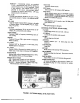

TRANSMITfER TUNING STEPS3. Your Siltroni.x 1011B will automatically transmit on
exactly the same frequency as the one to which you are
listening.
CD Make the following preliminary adjustments:
4. If it is desired to receive on lower Sideband, rotate
the SIDEBAND SELECTOR switch to the LSB position.
RECEIVER TUNING (AM)
Refer to the RECEIVE OPERATION paragraph above, and
perform all the steps.
CD After adjusting the DRIVER and the P .A. TUNE con-
trols for maximuIJ\ receiver noise, rotate the SIDE
BAND SELECTOR switch to the AM REC. mode.
a. Sideband selector switch in USB position.
b. Tuning dial to desired frequency.
c. Mic Gain at minimum.
d. Carrier Insertion to full CCW (MIN) position.
e. Meter Switch in P.A. CATHODE position.
f. Function Switch in REC position.
g. P .A. BIAS control on rear panel to full CCW
position.
h. Microphone with press-to-talk switch plugged into
Mic Jack on front panel.
@ Press the Mic switch and observe the meter for any
J' reading. Meter should read approximately O. If the
meter does not read approximately 0, it indicates that
the CARRIER is not completely balanced out. LOCate
the CARRIER BAL hole on the bottom cover. With
the Mic switch pressed, use an alignment tool and
adjust the carrier balance pot until the meter "dips"
at its lowest reading. This adjustment should not be
required often.
@ Rotate the tuning dial until an AM signal is heard.
-0 Pl~.'?! the SPOT switch in the ON (UP) position. This
removes the bias from the carrier oscillator, allowing
the carrier to be heard in the receiver.
0 Press the Mic Switch and with a screwdriver, adjust
the P .A. BIAS control located on the rear panel, until
the meter reads approximately 40 ma. P .A. Idling cur-
rent. This point is indicated on the meter scale by a
small triangular symbol. The permissible idling cur-
rent range is 30 to 50 ma. If the idling current tends
to creep upward slightly with warm-up, set it at 30 ma.
Excessive creep indicates that the P.A. tube is gassy,
and may need to be replaced soon. This adjustment
should not be required often.
0 Zero beat the carrier with the tuning dial.
@ Turn off the SPOT switch.
@ The AM station should be on frequency, with excel-
lent voice reception.
TRANSMITTER TUNING
I CAUTION I
READ CAREFULLY. BE SURE THAT YOU
UNDERSTAND AND REMEMBER THESE
NOTES WHEN TUNING THE TRANSMITTER.
0 If this is the first time you are tuning the .transmitter,
set DRIVER control, P.A. LOAD control, and P.A.
PLATE control to the straight up (12 0 'clock) posi-
tion. After gaining experience in tuning these con-
trols, they may be pre-set to previously determined
positions.
I. The most important detail to keep in mind when tun-
ing the transmitter portion of your Siltronix 1011 B is that
the P.A TUNE control must be resonated as quickly as
possible.
NOTE
! :1
2. The P.A. tube is dissipating all the power input when
it is not in resonance, and can be permanently damaged in
just a few seconds.
UP TO NOW THE TRANSMITTER HAS BEEN
"IDLING" AND mERE HAS BEEN NO PAR.
TICULAR TIME LIMIT INVOLVED. THE
FOLLOWING STEPS APPLY GRID DRNE,
AND REQUIRE C4UTION. OBSERVE THE
RECOMMENDED 30 SECOND TIME LIMIT.
3. Once resonance has been established, the P.A tube
can operate at full power input for quite a while, although
we recommend 30 seconds as a safe maximum. But it is
most important to realize that the 30 second limit assumes
that the P.A. TUNE control has been immediately reson-
ated. This rule applies generally to all transmitters.
@ Set METER SWITCH to the 5-METER position. Ro-
tate FUNCTION SWITCH to the TUNE-CW position
and:
4. Do not tune more often than necessary. The P.A
tube will last for many months, or even years, with normal
operation, but excessive tuning will shorten tube life.
a. Rotate DRNER control for maximum meter
reading.
.,