
Operating instructions

0 Carefully adjust the DRIVER and the P.A. TUNE
controls for maximum receiver noise.
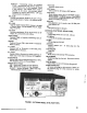
Before connecting any cables to the Siltronix lOll B trans-
ceiver, perform the following steps:
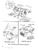
<D Locate the P.A. compartment and remove the packing
material from the P.A. tube.
NOTE
The DRIVER control resonates the transmitter
driver stages and the receiver RF amplifier
plate circuit. The P.A. TUNE and P.A. LOAD
controls adjust the input and output capacitors
in the transmitter power amplifier final plate
circuit, as well as the receiver RF amplifier grid
circuit. Proper adjustment of these controls in
the receive position will result in approximately
resonant conditions in the transmitter stages.
CD Rotate the Function Switch to the REC. position.
0 Rotate the AF GAIN control counter clockwise to
operate the power switch to the OFF position.
(4) Rotate the CARRIER INSERTION control full
counter clockwise to the minimum position.
CONNECTIONS
-0) Connect a wire from earth ground to the ground stud
located on the rear of the chassis. This is not essen-
tial, but is strongly recommended.
RECEIVER TUNING (88B)
Precise tuning of a single sideband signal is very important.
Do not be satisfied to merely tune until the voice can be
understood, but take the extra care of setting the dial to the
exact spot where the voice sounds natural. Above all, avoid
the habit of tuning so that the voice is pitched higher than
normal. This is an unfortunate habit practiced by quite a
number of operators.
Q) Connect a 50 or 75 ohm antenna feed.line to the
coaxial connector on rear panel. A 50 ohm dummy
load may also be used.
0 Connect the AC power cable to the Jones connector
on the rear panel.
(9 Connect the AC power cable to the proper voltage
.source.
The following points help to explain the effects of mis-
tuning:
1. If you tune so the received voice is higher than normal
pitch, you will then transmit off frequency, and your voice
will sound lower than normal pitch to the other station. He
will probably retune his dial to make you soun'd right. If
you keep this up, you will gradually waltz one another
across the band. If both of you are mistuning to an un-
natural higher pitch, you will waltz across the band twice as
fast. (And someone will no doubt be accused of frequency
drift.)
I WARNING_]
Dangerous high voltage is present on the plate
of the power amplifier whenever the power
supply is energized.
RECEIVE OPERATION
CD Rotate the A.F. GAIN control clockwise to about the
3 o'clock position. The power switch will operate,
applying voltage to the transceiver. The dial and
meter lights should illuminate.
2. Mistuning results in serious hannonic distortion on
the voice, and should be quite noticeable to the average ear.
Some will claim that if they don't know how the other per-
son's voice actually sounds, they can't tune him in properly,
but this is not true. With a little practice, it will be fairly
easy to tell. Some voices are relatively rich in harmonics,
and are easier to tune in than a person with a "flat" voice.
Also, a transmitter, which is being operated properly with
low distortion will be easier to tune in than one which is
being over-driven and is generating excessive distortion.
There is no mistaking when you have a station tuned right
on the nose. It will sound just like "AM" so to speak.
Mainly, avoid the habit of tuning so everyone sounds higher
than normal pitch, or like "Donald Duck". This is incor-
rect, unnecessary, and sounds terrible.
@ Wait approximately one minute to allow the tube fIla-
ments to reach operating temperature. During this
waiting period, perform the following steps:
a. Rotate Frequency Range switch to desired range.
b. Rotate Tuning Dial to desired frequency.
c. Rotate MIC. GAIN fully counter clockwise.
d. Set P.A. TUNE control to 12 o'clock position.
e. Set DRNER control to 12 o'clock position.
f. Set P .A. LOAD control to 12 o'clock position.
g. Rotate RF GAIN control to 3 o'clock position.
h. Place SIDEBAND SELECTORswitch in USB mode.
6