
Operating instructions
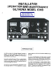

GENERAL
MOBILE INSTALLATION
The installation of the Siltronix 1011 B is not at all difficult,
and it involves only the placement of the transceiver in its
operational area (fixed or mobile); connection of power
(either 117 volts AC, or 12 volts DC); and the connection
of an antenna. The following paragraphs are therefore
devoted to the installation requirements involving micro.
phones, fIXed and mobile operation, and recommended
antenna types. Before actual installation, be sure to check
for possible shipment damage. Remove the cabinet (three
screws on each side), and check to make sure that all tubes
are fIrmly in place. Remove packing from around the P .A.
tube. -_.
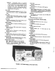
DC CONVERTER, MODEL 14A
For 12-14 volt DC operation in mobile installations, it will
be. necessary to use the 14A converter, which plugs directly
into the back of the IO11B in place of the AC power cord.
FIXED INSTALLATION
MOBILE ANTENNAS
The standard type mobile antennas designed for 10 meters
or CB band will perform well with the 101 lB. Generally
speaking, a full length 8 or 9 foot whip will be more effi-
cient than the shorter inductively loaded types.
Wcate the 1011B in an area which is well ventilated and
which provides complete operational freedom of the front
panel con trois. Connect the AC power cord to the 12 pin
Jones connector on the rear panel. If the 1011 B is a 117
volt model, plug the power cord into a standard 117 volt
50-60 Hz outlet having a capacity of at least 10 amps. If
the 101 I B is an Export model, it should be first set to the
proper voltage tap: 208, 220, or 240 volts, 50-60 Hz. Re-
move the cabinet, and locate the terminal strip near the top
of the power transformer. There are 3 terminal lugs and a
decal which indicates the voltage tap for each. Connection
has been made to the 220 volt tap at the factory. If your
supply voltage is 208 or 240 volts, unsolder the red wire
and move it accordingly.
MICROPHONE
The microphone input is designed for high impedance
microphones only. The choice of microphone is important
for good speech quality, and should be given serious con-
sideration. The crystal lattice filter in the transceiver pro-
vides all the restriction necessary on audio response, and
further restriction in the microphone is not required. It is
more important to have a microphone with a smooth, flat,
response throughout the speech range. The..microphone
plug must be a standard % in. diameter three contact type.
The tip connection is for push-to-talk relay control, the
ring connector is the microphone terminals, and the sleeve
is the common chassis ground. The microphone manu-
facturer's instructions should be followed in connecting
the microphone cable to the plug. Either hand-held or desk
type microphone with push-to-talk control will provide a
suitable installation. For VOX operation, this feature may
be disabled, if desired, by opening the microphone case and
permanently connecting the contacts which control the
microphone.
!
i
FIXED ANTENNA
A standard PL-239 coax connector plug will fit the antenna
connector on the rear panel of the 1011 B. For feed line
runs up to 50 feet, RG58 or RG59 is recommended. For
longer runs, RG8 or RG 11 produces less line loss, particu-
larly on 10 meters.
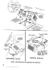
CONTROL FUNCTIONS, FRONT PANEL
Any of the common antenna systems designed for use on
the 10 meter amateur band will work well with the 1011 B.
However, the amateur should consider an antenna system
which best fits his operational requirements. For example,
a rotatable beam antenna is usually best suited for DX oper-
ation. Methods for constructing antennas and antenna
tuners are described in detail in the ARRL Antenna Hand-
book and similar publications. It is recommended that
these publications be consulted during the design of any
antenna system.
POWER ON-OFF SWITCH (On AF GAIN control)
Turns power supply On and OFF.
FUNC110N SWITCH (CAL. REC. TUNE-CW)
Calibrate -All voltages are applied to receiver.
Grounds cathode of V12. Dial adjustment can be
made at any 100 KHz point on the dial.
Receive -All voltages are applied to receiver. Normal
position for Push-to-talk or VOX operation of
transceiver.