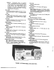
.,. Downloaded by RadioAmateur.EU The Siltronix Model 1011B Single SidebandTransceiveris designedto be used in SSB, AM, or CWmodesin the 10 meter amateurradio band. In addition, the 1011B is alsoa tunable receiverin the CBband. Powerinput exceeds260 watts, P.E.P.,on singlesideband, 60 watts on AM, and 180 watts on CW. The Modell 011B includesautomaticgain control (AGC),automatic levelcontrol (ALC), and grid block keying.
FREQUENCY RANGES 28.0-28.5MHz 28.5-29.0MHz 29.0-29.5MHz 29.2-29.7MHz 26.96-27.26MHz (Receiveonly) ( REAR PANEL CONTROLS AND CONNECTIONS P.A. BIAS Potentiometer,AUX RELAY jack, CW KEY jack, Outboard VFO Connector, HEAD PHONESjack, Fuse Holder,Antenna Connector,Jonesplug Powerconnector, S-MeterZero. OTHER CONTROLS AND CONNECTIONS POWER INPUT SingleSideband,Suppressed Carrier: 260 watts,P.E.P.
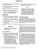
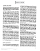
GENERAL The installation of the Siltronix 1011 B is not at all difficult, and it involves only the placement of the transceiver in its operational area (fixed or mobile); connection of power (either 117 volts AC, or 12 volts DC); and the connection of an antenna. The following paragraphs are therefore devoted to the installation requirements involving micro. phones, fIXed and mobile operation, and recommended antenna types. Before actual installation, be sure to check for possible shipment damage.
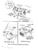
., I';;:::j ~ ~ --~'~--0--~ I~~ ,...~ <" I.~ -.; "..;;::: ALTERNATE ~ BRACKET LOCATION ,,:~~"""~ \\~~\' f} #6 x .5/16 SCREWS, '+ PLACES. FRONTBRACKET ALTERNATE ~ MOUNTING , .,#" ~."_..~~ ,...,. y./.' I ,, ,. TWO# 12-24 HEX HEAD /: SCREWS ~ ~ 8 ># 10 x 3/4 SEAT Mf:l' AL S CRE\'lS ~ 4 PLACES TRANSMISSION HUMP JII IIIIII .REAR BRACKET. PLUGS INTO SLOT' MADE BY FLAT WASHER BETWEEN CHASSIS AND BOTTOM COVER TRANSCEIVER,BOTTOMVIEW MOBILE MOUNTING, SIDE VIEW FIGURE 1.
TUNE-CW -Transmitting circuits are energized. CIS02 is disconnectedfrom ground, shifting the carrier frequencyinto the Cuterpassband.Carrier is fully inserted. P.A. cathode resistor, R406 is switched in the circuit, reducing input power. Transmitteris tuned in this position. CW transmissionsmadein this position. MIC. GAIN Controls potentiometer R1404 in the grid of V14A, and controls amount of audio to the balancedmodu- lator. R.F.
Beforeconnectingany cablesto the Siltronix lOll B transceiver,perform the following steps: 0
3. Your Siltroni.x 1011B will automatically transmit on exactly the same frequency as the one to which you are TRANSMITfER TUNING STEPS listening. CD Make the following preliminary adjustments: a. b. c. d. e. f. g. Sidebandselectorswitch in USBposition. Tuning dial to desiredfrequency. Mic Gain at minimum. CarrierInsertion to full CCW(MIN) position. Meter Switch in P.A. CATHODEposition. Function Switch in REC position. P.A. BIAS control on rear panel to full CCW position. h.
b. IMMEDIATELY rotate P.A. TUNE control for maximum meter reading. -nus is the critical "resonating" adjustment which must be done quickly to preserveP.A tube life. NOTE The Transceiver will not modulate with the Function Switch in the CAL position. Rotate P.A. LOAD control for maximum. AM TRANSMITTER TUNING d. Re-adjustP.A. TUNE control for maximum. This adjustmentshould be repeatedeachtime the P.A. load control is adjusted.
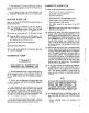
GENERAL DISCUSSION The Siltronix 1011B transceiverprovidessingle sideband, suppressedcarrier transceiveoperation, and generatesthe singlesidebandsignalby meansof a crystallattice filter. To permit a logical discussionof this mode of operation, certain definitions are necessary . h1 a normal AM signal (double sidebandwith carrier), a radio frequencysignalis modulatedwith anaudio frequency signal. This is consideredby many to be merely a caseof varying the amplitude of the carrier at an audio rate.
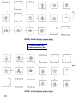
I ~ I I V2 TRANS MIX 12BE6 L V4 V3 DRIVER 6GK6 POWER AMP 6LF6 ANT j- ~ I V10 AGC/ALC Q3 CAR OSC AMP 6AV6 2N706 L_- V7 FIRST IFAMP 12BA6 Vl PI NET VFO AMP 12BA6 __I I V14A MIC AMP 1/2 12AX7 V14B AF AMP 1/212AX7 V13 BAL MOD 6JH8 I I XTAL FILTER 5500 Xc .. L ...:.:.:. ..,;;j" FIGURE 3. BLOCK DIAGRAM, TRANSMIT MODE Downloaded by RadioAmateur.EU V9A PRODUCT DET 1/212AX7 I VB I I SECOND IFAMP 12BA6 L___J L I. 1---_J i ANT ~ V9B REC AFAMP 1/2. 12.
of the First IF Amplifier is controlled through the Automatic uvel Control (ALC) network (using the AGC Amplifier VIO) to control the gain of the stage in response to the average input power to the Power Amplifier. This ALC system \vill compensate for any extremely strong input signals, but does not completely eliminate the necessity of proper adjustment of the Mic. Gain Control.
~ -,iIt-i ;'1t- Authorities agreethat the averagevoice power is 20 to 20db below peakvoice power. Normally, some peak clipping in the power amplifier can be tolerated,and a peak-to-average ratio of only 6 db may sometimesoccur. Under suchconditions, the averagepower input will be 80 watts,and averageplate current will be 100ma. With power amplifier efficiency of 65 percent,plate dissipationwill be approximately 5498 SSOO 26 watts.
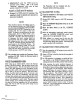
Dle alignment procedures presented in this section are routine touch-up procedures for all tuned circuits and other adjustments. It is recommended that the procedures be performed in the order presented. However, if complete realignment is not required (as may be the case when just one tube is replaced), perform just those procedures required. Refer to Figures 6 and 7 for component placement. 2.
Downloaded by RadioAmateur.EU FIGURE 6. SILTRONIX MODEL 10118 TOP VIEW.
for the meter to "peak" abovethe 100ma. plateau on either side of resonance.If there is sucha peak, adjust C40l, the P.A NEUTRALIZING trimmer to suppressthe peak. Whenproperly neutralized, the meter reading will hold steadily at 100 ma. except for the sharp dip at resonance,but there will be no peakabovethe 100ma. level. 0 Increasegain of audio generator until the wattmeter reads40 watts. Sweepgeneratordown to 200 Hertz and adjust the USB carrier oscillator trimmer, C1S03,for a readingof 10watts.
, TABLE 1. VOLTAGE AND RESISTANCE MEASUREMENTS Voltage measurements were taken using a HEWLETT taken using a SIMPSON MOdel 260 Volt-Ohm meter. TUBE TYPE R = Rec. T = Trans. VI 12BA6 R Volts T Volts Ohms VFOAmp. Driver V5 6BZ6 Rec.RF. Model 410C/B VTVM. 1 2 3 1.2K 12.6AC 45 12.6AC 50 0 0 0.2 0 -1.2 -1.0 0 0 12.6AC 12.6AC 250 -2 250 135 lOOK 0 0 0 0 .02 R Volts T Volts Ohms 0 0 -6.7 -6.7 lOOK 0 0 0 63AC 63AC 10 0 0 0 RVolts T Volts 0 0 0 6.3AC 0 0 0 6.3AC 0.
TABLE 2. TROUBLESHOOTING GUIDE DEFECT POSSIBLECAUSE PA Idling Current Unstable 1. DefectivePowerAmplifier Tube(V4). 2. DefectiveBIAS control and/or associatedcomponents. 3. Defectivebias powersupply. Inability to Load per OperationInstructions 1. 2 3. 4. Insufficient Sideband Suppression 1. CarrierOscillator(Q3) operatingon incorrect frequency. 2. Crystal fllter defectiveor mistuned. Insufficient Carrier Suppression 1. TubeV13 defective. 2. TransformerT1301 defectiveor mistuned. 3.
[PARTS RESISTORS RlOO6 RlOO7 All resistorsare 1,2watt 10% tolerance,unlessotherwisenoted. RlOl 82 Ohm Rl02 47K Rl03 10K.2W Rl04 56 Ohm R20l 27K R202 lOOK R203 lOOK RII05 R1201 R204 10K.2W R1202 470K 2.7K lOOK lOOK 10 Ohm 100Ohm 100 Ohm 25K BiasPot. 4.7K IK 3 Ohm-5W 100 Ohm-SW 2.7K l5K lOOK 220K 470 Ohm 10K 25K R.F. GainPot 10K 470K 47K 1.5K 33K-2W lK R1203 R1301 R205 R206 R30l R302 -R303 .
CI08 C302 C303 C304 2pf Disc 2pf Disc .01 +80-20% 500V Disc .002 20% 1 KV Disc .05 200V Mylar .01 +80-20% 500V Disc 470pf SM 2pf SOOVCeramic .00220% lKV Disc 20pf Driver Tuning 20pf Driver Tuning .00220% lKV Disc 51OpfSM .00220% lKV Disc C305 5pf .CI09 ClIO C111 .C201 C202 C203 " C204 C205 C2A , C2B C401 C402 C403 C404 C40S C4Q6 ..~.C407 .
WARRANTY POliCY Silt."On~ Corporation walTants this equipment against def~ts in material or workmanship,except for tubes, transistors,and diodes. under nolmal servicefor a period of 6 months from date of original purchase: Tubes,transist~rs,and diodes are coveredunder the warranty policy for Ii period of 90 days. This warranty is valid only if the enclosedcard is properly filled in and mailed to thefactory within ten days of date of purchase. Do not ship to the factory without prior authorization.
Downloaded by RadioAmateur.
Downloaded by RadioAmateur.
~ ~ T.- "1~~~~~~.~J. - RCA- ., - -. --- ---'"\..1- .-J mc~ WF 2Mr ~I. ~I'I 0 0 i i...- 0 Dl111 I" cms _~I' K -I- .. ~ ,"'- I I , ~I I I I I I I I .I I .
~ ':" :-J :...
Downloaded by RadioAmateur.