
Specifications
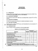

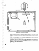


FIGURE 12·2.
REMOVAUREPLACEMENT
OF
CONTROL PCB
c.
Remove the
PCB.
~
~
()
i
I
E
E
E
E
E
E
~
~
I
~
E
12·4
Plug
In
the
three
circuit
cables.
Be
sure the cllble.
are
fuUy
Inserted Into position.
Remove
and
retain the
five mounting screws.
Place the Control PCB on the drive at an angle
••••
hown. to allow the cables to be plugged
in.
!Place
".....
the edge
with
the cut-out under the
lip
of
the
lid..
rail.
but
over the stand-offs.
'J
b.
a.
c.
h.
After
the
five
mounting
saews
have been properly tightened.
fiD
the
saew
heads
with
glyptol.
d. Replace the Front Panel
Rail
Assembly and
mountir:'9
screws.
a. Remove and retain the
five
mounting
screws.
g. Push the brake pad
awa~J
:
·mn
the spindle
,·otor
to
see that the brake has sufficient stroke to
dear
the
spincUe.
The
stroke should
be
about
0.020
lnch
(O.~
mm).
. .
b.
Lift
the
Control
PCB
and
Front Panel
Rall
Assembly
about
2 inches
(51
mm)
and
unplug the
spindle.
stepper
t
and
flex
circuits.
12.7.2
Replacement
of
Control
PCB
The
foUowing
steps
give
the sequence
with
which
to
install
a control PCB (see
figure
12-2):
12.7 REMOVAL
AND
REPLACEMENT PROCEDURES
The
foUowing
steps define the process to
be
followed
for
the removal
of
the Control PCB (see
figure
12·2):
I
12.7.1 Removal
of
Control
PCB