
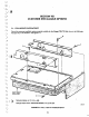
Specifications


physical position "drift" of the index pulse as a functton of drive
~emperature.
Gap 1 should
be
at
least
22
~1es
(30
bytes recommended)
10llg
to correspond
with
the head
switching
time
and
index drift.
Gap
1 is immediately
follow-
ed
by
a sync
field
for the 10
field
of
the
first
sector.
6.2.2
Gap
2
Following
the 10 field. and separating it
from
the data
field,
is Gap 2. Gap 2 provides a known area
for
the data
field write update to occur. The remainder of
this
gap
Also
serves as
the
sync-~p
area
for
the
data
field address
mark. The length of Gap 2
is
determined
by
the data separator lock-up performance.
6.2.3 Gap 3
Gap
3,
following
the
data
field. is a
speed
variation tolerance area.
This
aUows
for a situation where a track has
I
been
formatted while
the
disk is running
two
percent
slo'.uer (3531
rpm).
then
write
updated
with
the
disk running
at highest speed (3603
rpm).
Gap 3 should
be
at
least 15 bytes In length
(this
includes
two
bytes
for
write tum off).
6.2.4
Gap
4
Gap 4
is
a
speed
tolerance
buffer
for
the entir4 track. This allows the disk to rotate at
the
highest rated speed
without overflowing the track dUring a format operation. The format operation which writes the 10
fields,
begins
with
the
first
encountered
index
and
continues
to the next index.
6.3 WRITE PRECOMPENSATION
Whenever
two
bits
are
written
in
close proximity to each other, a phenomenon called pulse superposition occurs,
which
tends
to
cause the two
bits
to move
away
from
each other.
This
is
a large factor contributing to bit shift. Other
phenomena
such
as random noise, speed variation. etc..
will
also cause bit
shift,
but to a lesser degree.
The
effect
of
bit
shift
can
be
reduced
by
a technique
call
precompensation,
which.
by
detecting which
bits
wUI
occur
early
and
which
bits
will
occur late, can effectively minimize the
shift
by
writing these
bits
in
the opposite direction
of
the
expected
shift.
Bit
shift
is
more
apparent
on the innermost dat tracks due to
pulse
crowding. Therefore.
precompensation should only be at track numbers greater than or equal
to
128.
The
optimum amount
of
precompensation
for
a
706/712
drive
is
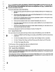
12 nsec for both early and late written bits. Table 6-1 shows various
bit
pat-
terns for
precompensation.
Precompensation
pattern detection
bits
are shifted
through
a 4-bit shift register. The bit
is
written out of the third position.
1(
TABLE
~1.
WRITE'
PRECOMPENSATION
WRITE
POS,nON
DtREcnON OF SHIFT
o 0 0 0
=ON TIME CLOCK
000
1
=LATE CLOCK
001
0
=ON TIME DATA
001
1
=
EARLY
DATA
o 1 0 0
::
o 1 0 1
::
o 1 1 0
= LATE DATA
o 1 1 1
::
ON TIME DATA
100
0
=
EARL
Y CLOCK
100
1
::
ON TIME CLOCK
101
0
::
ON
TIt.4E
DATA
10'
1
::
1 1 0 0
::
1
101
=
1
110
=LATE DATA
111
1
;:;
ON TIME DATA
BIT IS WRITTEN CUT OF THIRD POSITION
310»24
8·2
)