
Specifications


.,
.'@
-
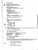
DATA
TRACKS
40mm
DISK
10
TRt<
00
130
mm
DISK
00
HEAD SHIPPING ZONE
CYLINDER
353
..
· l
.
"
u
"
I,
• lJ
-
.:1
:
..
~
-
...
-
..
....
:~
.•
l
FIGURE 1·5. SHIPPING ZONE
._'
..
,
t I
..
,
.'
,
..
• t•
.'
..
,
1.5.3
Track Acceaalng
Read/write head positioning
is
accomplished
by:
a. Deactivating the
WRITE
GATE.
b.
Activating
the
appropriate
DRIVE
SELECT
line
.
c. Being
in the
READY
condition
with
SEEK
COMPlETE
true.\
d. Selecttng the appropriate direction.
e. Pulsing the STEP
Un
•.
f.
Checking
for
the edge of the -SEEK
COMPLETE
line
(changing
from
false
to true).
.
·
..
...
...
( t
Stepping
can
occur
at
either the
normal
or
buffered rate. DUring normal stepping,-the heads
are
repositioned at the
rate of incoming step pulses. In the
case
of
buffered stepping,
Incoming
step pulses
are
received at a high rate and
are
buffered
Into
counters.
When
all
of
the
steps
have
been received, they
are
Issued
to
the
stepper drivers at a
ramped stepping rate.
Each
pulse
will
cause
the heads
to
move either one track In or one track out,
depending
on the
level
of
the
DIREC-
TION
IN
line. A true
on
the
DIRECTION
IN
line
wUI
cause an
Inward
seek: a
false
will
result
in
an outward seek
toward track
00
.
.
t'
'·7