
User manual


Preliminary
...the world's most energy friendly microcontrollers
2012-05-15 - TBD 18
www.energymicro.com
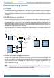
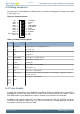
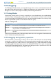
9.3 Debug connector
This connector is used for Debug In and Debug Out (see chapter on Debugging). The pinout is described
in Table 9.2 (p. 18) .
Figure 9.3. Debug Connector
VTARGET
# TRST
TMS/SWDIO
TCK/SWCLK
RTCK
TDO/SWO
# RESET
TDI
NC
GND
GND
GND
GND
GND
GND
GND
Cable Detect
GND
2
4
8
10
12
14
16
6
18
20
1
3
7
9
11
13
15
5
17
19
PD
PD
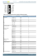
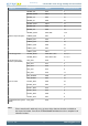
Table 9.2. Debug connector pinout
Pin
number
Function Note
1 VTARGET Target voltage on the debugged application.
2 NC Not Connected
3 #TRST JTAG tap reset
5 TDI JTAG data in
7 TMS/SWDIO JTAG TMS or Serial Wire data I/O
9 TCK/SWCLK JTAG TCK or Serial Wire clock
11 RTCK JTAG RTCK
13 TDO/SWO JTAG TDO or Serial Wire Output
15 #RESET Target MCU reset
17 PD This pin has a 100k pulldown.
18 Cable detect This signal must be pulled to ground by the external debugger or application for cable
insertion detection.
19 PD This pin has a 100k pulldown.
4, 6, 8,
10, 12,
14, 16,
20
GND
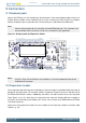
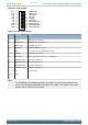
9.4 Trace Header
A header with connections to the Embedded Trace Module (ETM) in the EFM32 Giant Gecko MCU is
provided on the reverse side of the PCB. The header is not mounted by default, but a 20-pin, 1.27mm
pitch SMD header can be soldered on to allow an external trace emulator to be connected.
In addition to the serial wire debug pins, this header also contains the ETM_CLK and ETM_TD signals.
The pinout is described in Table 9.3 (p. 19) . Please refer to the kit assembly drawing to locate the
trace header, which has the reference P200.