
User manual


Preliminary
...the world's most energy friendly microcontrollers
2012-05-15 - TBD 15
www.energymicro.com
9 Connectors
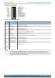
9.1 Breakout pads
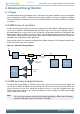
Many of the EFM32's pins are routed out to "breakout pads" at the top and bottom edges of the kit. A
2.54mm pitch pin header can be soldered in for easy access to these pins. Most I/O pins are available,
with the exception of pins used to drive the LCD and some pins used to drive the NAND flash.
Note
Some of the breakout pads are shared by on-board EFM peripherals. The schematic must
be consulted to make sure that it is OK to use a shared pin in your application.
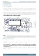
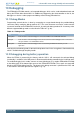
Figure 9.1. Breakout pads and Expansion Header
SW CLK
5V
PA1 2
PA1 3
PA1 4
GND
PE0
PE1
PE2
PE3
GND
PC0
PC1
PC2
PC7
GND
PF8
PF9
VM CU
3V3
3V3
5V
PD6
PD5
PD4
PD3
PD2
PD1
PD0
VM CU
20
18
16
14
12
10
8
6
4
2
GND
RESET#
SW DIO
SW O
5V
PB10
PB9
GND
PB11
PB12
PD15
GND
PD0
PD1
PD2
PD3
PD4
PD5
GND
PD6
PD7
PD8
PD13
PD14
VM CU
3V3
Debug Pins
Expansion Header
19
17
15
13
11
9
7
5
3
1
GND
PC0
PC3
PC4
PC5
PB11
PB12
PD7
PC6
GND
Debug Connector
Note
Pins PC3, PC4, PC5 and PC6 are also available as surface mounted pads beneath the
USB Micro-AB connector
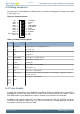
9.2 Expansion header
On the right hand side of the board an angled 20 pin expansion header is provided to allow connection of
peripherals or plugin boards. The connecter contains a number of I/O pins that can be used with most of
the EFM32 Giant Gecko's features. Additionally, the VMCU, 3V3 and 5V power rails are also exported.
Figure Figure 9.1 (p. 15) shows the pin assignment of the expansion header. With the exception of
a few pins, most of the Expansion Header's pins are the same as those on the EFM32 Gecko or EFM32
Tiny Gecko starter kits.
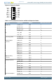
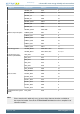
Some of the chip peripheral functions that are available on the Expansion Header are listed in table
Table 9.1 (p. 16) .