
User manual

...the world's most energy friendly microcontrollers
2012-04-24 - Giant Gecko Family - d0053_Rev0.96 99
www.energymicro.com
up. At startup the EFM32GG loads the stack pointer and program entry point from memory, and starts
execution.
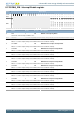
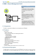
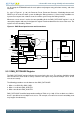
As seen in Figure 9.1 (p. 99) the Power-on Reset, Brown-out Detectors, Watchdog timeout and
RESETn pin all reset the whole system including the Debug Interface. A Core Lockup condition or a
System reset request from software resets the whole system except the Debug Interface.
Whenever a reset source is active, the corresponbding bit in the RMU_RSTCAUSE register is set. At
startup the program code may investigate this register in order to determine the cause of the reset. The
register must be cleared by software.
Figure 9.1. RMU Reset Input Sources and Connections.
SYSREQRST
WDOG
Reset Management Unit
PORESETn
SYSRESETn
LOCKUP
POWERONn
BROWNOUT_UNREGn
RESETn
Filter
LOCKUPRDIS
V
DD
POR
BOD
Core
Debug
Interface
Cortex-M3
Peripherals
V
DD
_REGULATED
RMU_RSTCAUSE
BROWNOUT_REGn
RCCLR
Edge-to-pulse
filter
BOD
AVDD0
BROWNOUT_AVDD0
BOD
AVDD1
BROWNOUT_AVDD1
BOD
EM4 wakeup
em4
Backup m ode
Backup m ode exit
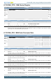
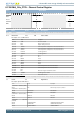
9.3.1 RMU_RSTCAUSE Register
The RMU_RSTCAUSE register indicates the reason for the last reset. The register should be cleared
after the value has been read at startup. Otherwise the register may indicate multiple causes for the
reset at next startup.
The following procedure must be done to clear RMU_RSTCAUSE:
1. Write a 1 to RCCLR in RMU_CMD
2. Write a 1 to bit 0 in EMU_AUXCTRL
3. Write a 0 to bit 0 in EMU_AUXCTRL
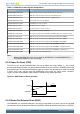
RMU_RSTCAUSE should be interpreted according to Table 9.1 (p. 100) . X bits are don't care. Notice
that it is possible to have multiple reset causes. For example, an external reset and a watchdog reset
may happen simultaneously.