
User manual


...the world's most energy friendly microcontrollers
2012-04-24 - Giant Gecko Family - d0053_Rev0.96 88
www.energymicro.com
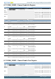
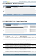
Bit Name Reset Access Description
When this bit is 1, it indicates that the peripheral connected as the input to this DMA channel is requesting the controller to service
the DMA channel. The controller services the request by performing the DMA cycle using single DMA transfers.
5 CH5SREQSTATUS 0 R Channel 5 Single Request Status
When this bit is 1, it indicates that the peripheral connected as the input to this DMA channel is requesting the controller to service
the DMA channel. The controller services the request by performing the DMA cycle using single DMA transfers.
4 CH4SREQSTATUS 0 R Channel 4 Single Request Status
When this bit is 1, it indicates that the peripheral connected as the input to this DMA channel is requesting the controller to service
the DMA channel. The controller services the request by performing the DMA cycle using single DMA transfers.
3 CH3SREQSTATUS 0 R Channel 3 Single Request Status
When this bit is 1, it indicates that the peripheral connected as the input to this DMA channel is requesting the controller to service
the DMA channel. The controller services the request by performing the DMA cycle using single DMA transfers.
2 CH2SREQSTATUS 0 R Channel 2 Single Request Status
When this bit is 1, it indicates that the peripheral connected as the input to this DMA channel is requesting the controller to service
the DMA channel. The controller services the request by performing the DMA cycle using single DMA transfers.
1 CH1SREQSTATUS 0 R Channel 1 Single Request Status
When this bit is 1, it indicates that the peripheral connected as the input to this DMA channel is requesting the controller to service
the DMA channel. The controller services the request by performing the DMA cycle using single DMA transfers.
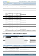
0 CH0SREQSTATUS 0 R Channel 0 Single Request Status
When this bit is 1, it indicates that the peripheral connected as the input to this DMA channel is requesting the controller to service
the DMA channel. The controller services the request by performing the DMA cycle using single DMA transfers.
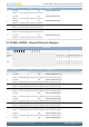
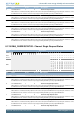
8.7.20 DMA_IF - Interrupt Flag Register
Offset Bit Position
0x1000
31
30
29
28
27
26
25
24
23
22
21
20
19
18
17
16
15
14
13
12
11
10
9
8
7
6
5
4
3
2
1
0
Reset
0
0
0
0
0
0
0
0
0
0
0
0
0
Access
R
R
R
R
R
R
R
R
R
R
R
R
R
Name
ERR
CH11DONE
CH10DONE
CH9DONE
CH8DONE
CH7DONE
CH6DONE
CH5DONE
CH4DONE
CH3DONE
CH2DONE
CH1DONE
CH0DONE
Bit Name Reset Access Description
31 ERR 0 R DMA Error Interrupt Flag
This flag is set when an error has occurred on the AHB bus.
30:12 Reserved
To ensure compatibility with future devices, always write bits to 0. More information in Section 2.1 (p. 3)
11 CH11DONE 0 R DMA Channel 11 Complete Interrupt Flag
Set when the DMA channel has completed its transfer. If the channel is disabled, the flag is set when there is a request for the channel.
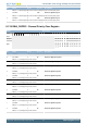
10 CH10DONE 0 R DMA Channel 10 Complete Interrupt Flag
Set when the DMA channel has completed its transfer. If the channel is disabled, the flag is set when there is a request for the channel.
9 CH9DONE 0 R DMA Channel 9 Complete Interrupt Flag
Set when the DMA channel has completed its transfer. If the channel is disabled, the flag is set when there is a request for the channel.
8 CH8DONE 0 R DMA Channel 8 Complete Interrupt Flag
Set when the DMA channel has completed its transfer. If the channel is disabled, the flag is set when there is a request for the channel.
7 CH7DONE 0 R DMA Channel 7 Complete Interrupt Flag
Set when the DMA channel has completed its transfer. If the channel is disabled, the flag is set when there is a request for the channel.
6 CH6DONE 0 R DMA Channel 6 Complete Interrupt Flag
Set when the DMA channel has completed its transfer. If the channel is disabled, the flag is set when there is a request for the channel.
5 CH5DONE 0 R DMA Channel 5 Complete Interrupt Flag