
User manual


...the world's most energy friendly microcontrollers
2012-04-24 - Giant Gecko Family - d0053_Rev0.96 793
www.energymicro.com
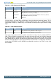
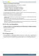
Table 33.12. LCD Animation Shift Register
AREGnSC, n = A
or B
Mode Description
00 NOSHIFT No Shift operation
01 SHIFTLEFT Animation register is shifted left (LCD_AREGA is shifted every odd state,
LCD_AREGB is shifted every even state)
10 SHIFTRIGHT Animation register is shifted right (LCD_AREGA is shifted every odd state,
LCD_AREGB is shifted every even state)
11 Reserved Reserved
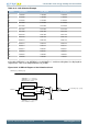
The two registers are either OR’ed or AND’ed to achieve the displayed animation pattern. This is
controlled by ALOGSEL in LCD_BACTRL as shown in Table 33.13 (p. 793) . In addition, the regular
segment data SEGD0[7:0] / SEGD0[15:8] is OR’ed with the animation pattern to generate the resulting
output.
Table 33.13. LCD Animation Pattern
ALOGSEL Mode Description
0 AND LCD_AREGA and LCD_AREGB are AND’ed together
1 OR LCD_AREGA and LCD_AREGB are OR’ed together
Each state is displayed one CLK
EVENT
period, see Section 33.3.10 (p. 791) . By reading ASTATE in
LCD_STATUS, software can identify which state that is currently active in the state sequence. Note that
the shifting operation is performed on internal registers that are not accessible in SW (when reading
LCD_AREGA and LCD_AREGB, the data that was original written will also be read back). The SW must
utilize the knowledge about the current state (ASTATE) to calculate what is currently output. ASTATE is
cleared when LCD_AREGA or LCD_AREGB are updated with new values. See Table 33.14 (p. 794)
for an example.