
User manual

...the world's most energy friendly microcontrollers
2012-04-24 - Giant Gecko Family - d0053_Rev0.96 790
www.energymicro.com
33.3.7.2 Framerate Division Register
The framerate is set in the CMU by programming the framerate division bits FDIV in CMU_LCDCTRL.
This setting should not be changed while the LCD driver is running. The equation for calculating the
resulting framerate is given from Equation 33.1 (p. 790)
LCD Framerate Calculation
LFACLK
LCD
= LFACLK
LCDpre
/(1 + FDIV) (33.1)
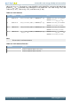
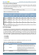
Table 33.9. LCD Framerate Conversion Table
Resulting Framerate, CLK
FRAME
(Hz)
LFACLK
LCDpre
= 2
kHz
LFACLK
LCDpre
= 1
kHz
LFACLK
LCDpre
=
0.5 kHz
LFACLK
LCDpre
=
0.25 kHz
MUX Mode
Frame- rate
formula
Min Max Min Max Min Max Min Max
Static LFACLK
LCD
/2 128 1024 64 512 32 256 16 128
Duplex LFACLK
LCD
/4 64 512 32 256 16 128 8 64
Triplex LFACLK
LCD
/6 43 341 21 171 11 85 5 43
Quadruplex LFACLK
LCD
/8 32 256 16 128 8 64 4 32
Sextaplex LFACLK
LCD
/12 21.33 170.67 10.67 85.33 5.33 42.67 2.67 21.33
Octaplex LFACLK
LCD
/16 16 128 8 64 4 32 2 16
Table settings: Min: FDIV = 7, Max: FDIV = 0
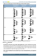
33.3.8 Data Update
The LCD Driver logic that controls the output waveforms is clocked on LFACLK
LCDpre
. The LCD data and
Control Registers are clocked on the HFCORECLK. To avoid metastability and unpredictable behavior,
the data in the Segment Data (SEGDn) registers must be synchronized to the LCD driver logic. Also,
it is important that data is updated at the beginning of an LCD frame since the segment waveform
depends on the segment data and a change in the middle of a frame may lead to a DC-component in that
frame. The LCD driver has dedicated functionality to synchronize data transfer to the LCD frames. The
synchronization logic is applied to all data that need to be updated at the beginning of the LCD frames:
• LCD_SEGDn
• LCD_AREGA
• LCD_AREGB
• LCD_BACTRL
The different methods to update data are controlled by the UDCTRL bits in LCD_CTRL.
Table 33.10. LCD Update Data Control (UDCTRL) Bits
UDCTRL Mode Description
00 REGULAR The data transfer is controlled by SW and data synchronization is
initiated by writing data to the buffers. Data is transferred as soon as
possible, possibly creating a frame with a DC component on the LCD.
01 FCEVENT The data transfer is done at the next event triggered by the Frame
Counter (FC). See Section 33.3.10 (p. 791) for details on how to
configure the Frame Counter. Optionally, the Frame Counter can also
generate an interrupt at every event.
10 FRAMESTART The data transfer is done at frame-start.