
User manual


...the world's most energy friendly microcontrollers
2012-04-24 - Giant Gecko Family - d0053_Rev0.96 779
www.energymicro.com
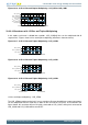
1/3 bias and duplex multiplexing - LCD_SEG0
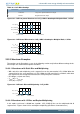
The LCD_SEG0 waveform on the left is just an example to illustrate how different segment waveforms
can be multiplexed with the COM lines in order to turn on and off LCD pixels. As illustrated in the
figures below, this waveform will turn ON pixels connected to LCD_COM0, while pixels connected to
LCD_COM1 will be turned OFF.
Figure 33.13. LCD 1/3 Bias and Duplex Multiplexing - LCD_SEG0
V
LC0
(V
LCD
)
V
LC3
(V
SS
)
Frame Start Frame End
V
LC1
(2/3V
LCD
)
V
LC2
(1/3V
LCD
)
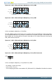
Figure 33.14. LCD 1/3 Bias and Duplex Multiplexing - LCD_SEG0 Connection
com1
com0
seg0
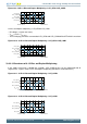
1/3 bias and duplex multiplexing - LCD_SEG0-LCD_COM0
• DC voltage = 0 (over one frame)
• V
RMS
= 0.75 × V
LCD_OUT
• The LCD display pixel that is connected to LCD_SEG0 and LCD_COM0 will be ON with this waveform
Figure 33.15. LCD 1/3 Bias and Duplex Multiplexing - LCD_SEG0-LCD_COM0
V
LC3
(V
SS
)
V
LC0
(V
LCD
)
V
LC1
(2/3V
LCD
)
V
LC2
(1/3V
LCD
)
-V
LC0
(V
LCD
)
-V
LC1
(2/3V
LCD
)
-V
LC2
(1/3V
LCD
)
Frame Start Fram e End
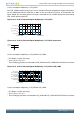
1/3 bias and duplex multiplexing - LCD_SEG0-LCD_COM0
• DC voltage = 0 (over one frame)
• V
RMS
= 0.33 × V
LCD_OUT
• The LCD display pixel that is connected to LCD_SEG0 and LCD_COM1 will be OFF with this waveform