
User manual


...the world's most energy friendly microcontrollers
2012-04-24 - Giant Gecko Family - d0053_Rev0.96 777
www.energymicro.com
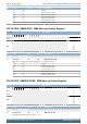
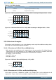
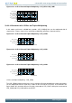
Figure 33.5. LCD 1/2 Bias and Duplex Multiplexing - LCD_COM0
V
LC0
(V
LCD
)
V
LC1
(1/2V
LCD
)
V
LC3
(V
SS
)
Frame Start Frame End
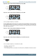
Figure 33.6. LCD 1/2 Bias and Duplex Multiplexing - LCD_COM1
V
LC0
(V
LCD
)
V
LC1
(1/2V
LCD
)
V
LC3
(V
SS
)
Frame Start Frame End
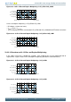
1/2 bias and duplex multiplexing - LCD_SEG0
The LCD_SEG0 waveform on the left is just an example to illustrate how different segment waveforms
can be multiplexed with the LCD_COM lines in order to turn on and off LCD pixels. As illustrated in the
figures below, this waveform will turn ON pixels connected to LCD_COM0, while pixels connected to
LCD_COM1 will be turned OFF.
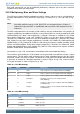
Figure 33.7. LCD 1/2 Bias and Duplex Multiplexing - LCD_SEG0
V
LC0
(V
LCD
)
V
LC1
(1/2V
LCD
)
V
LC3
(V
SS
)
Frame Start Frame End
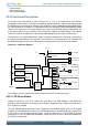
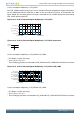
Figure 33.8. LCD 1/2 Bias and Duplex Multiplexing - LCD_SEG0 Connection
com1
com0
seg0
1/2 bias and duplex multiplexing - LCD_SEG0-LCD_COM0
• DC voltage = 0 (over one frame)
• V
RMS
= 0.79 × V
LCD_OUT
• The LCD display pixel that is connected to LCD_SEG0 and LCD_COM0 will be ON with this waveform.