
User manual

...the world's most energy friendly microcontrollers
2012-04-24 - Giant Gecko Family - d0053_Rev0.96 776
www.energymicro.com
Table 33.3. LCD Wave Settings
WAVE Mode Wave mode
0 LowPower Low power optimized waveform output
1 Normal Regular waveform output
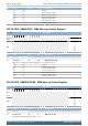
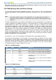
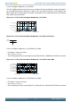
Figure 33.2. LCD Low-power Waveform for LCD_COM0 in Quadruples Multiplex Mode, 1/3 Bias
V
LC0
(V
LCD
)
V
LC1
(2/3V
LCD
)
V
LC3
(V
SS
)
V
LC2
(1/3V
LCD
)
Frame Start Frame End
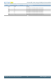
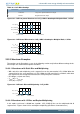
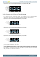
Figure 33.3. LCD Normal Waveform for LCD_COM0 in Quadruples Multiplex Mode, 1/3 Bias
V
LC0
(V
LCD
)
V
LC1
(2/3V
LCD
)
V
LC3
(V
SS
)
V
LC2
(1/3V
LCD
)
Frame Start Frame End
33.3.3 Waveform Examples
The numbers on the illustration's y-axes in the following sections only indicate different voltage levels.
All examples are shown with low-power waveforms.
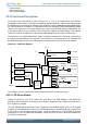
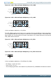
33.3.3.1 Waveforms with Static Bias and Multiplexing
• With static bias and multiplexing, each segment line can be connected to LCD_COM0. When the
segment line has the same waveform as LCD_COM0, the LCD panel pixel is turned off, while when
the segment line has the opposite waveform, the LCD panel pixel is turned on.
• DC voltage = 0 (over one frame)
• V
RMS
(on) = V
LCD_OUT
• V
RMS
(off) = 0 (V
SS
)
Figure 33.4. LCD Static Bias and Multiplexing - LCD_COM0
Fram e Start Fram e End
V
LC0
(V
LCD
)
V
LC3
(V
SS
)
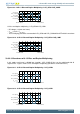
33.3.3.2 Waveforms with 1/2 Bias and Duplex Multiplexing
In this mode, each frame is divided into 4 periods. LCD_COM[1:0] lines can be multiplexed with all
segment lines. Figures show 1/2 bias and duplex multiplexing (waveforms show two frames)