
User manual


...the world's most energy friendly microcontrollers
2012-04-24 - Giant Gecko Family - d0053_Rev0.96 774
www.energymicro.com
• Frame Counter
• LCD frame interrupt
• Direct segment control
33.3 Functional Description
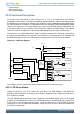
An overview of the LCD module is shown in Figure 33.1 (p. 774) . In its simplest form, an LCD driver
would apply a voltage above a certain threshold voltage in order to darken a segment and a voltage below
threshold to make a segment clear. However, the LCD display segment will degrade if the applied voltage
has a DC-component. To avoid this, the applied waveforms are arranged such that the differential voltage
seen by each segment has an average value of zero, and such that the RMS voltage (or differential sum
of the two waveforms for fast response LCDs) is below the segment threshold voltage if the segment
shall be transparent, and above the segment threshold voltage when the segment shall be dark.
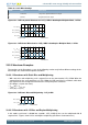
The waveforms are multiplexed between eight (1-8) different common lines and 20-36 segment lines
to support up to 288 different LCD segments. The common lines and segment lines can be enabled or
disabled individually to prevent the LCD driver from occupying more I/O resources than required.
Figure 33.1. LCD Block Diagram
LCD
voltage
generator
V
INT
V
EXT
V
BOOST
V
LC
1
V
LC
0
V
LC
1
V
LC
0
Disable
SEG out
Disable
COM out
LCD_SEGx
LCD_COMx
VLCDSEL
LCD control and
status
LCD segment
data register
LCD anim ation
registers
LCD
sequence
generator
Contrast and bias setting
Mux and framerate setting
Display data
Special
effects
LCD_BEXT
Data bus
LFACLK
LCD
LCD_BCAP_P
LCD_BCAP_N
V
LC
2
V
LC
4
V
LC
3
V
LC
2
V
LC
3
V
LC
4
4x
32x SEG
4x SEG/COM
For simplicity, only one segment pin and one common terminal is shown in the figure.
33.3.1 LCD Driver Enable
Setting the EN bit in LCD_CTRL enables the LCD driver. The MUX bitfield in LCD_DISPCTRL
determines which COM lines are driven by the LCD driver. By default, LCD_COM0 is driven whenever
the LCD driver is enabled.
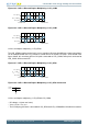
The LCD_SEGEN register determines which segment lines are enabled. Segment lines can be enabled
in groups of 4 and disabled in groups of 4 or individually disabled. To enable output on segment lines
0-7 for instance, the two lowest segment groups, set the two lowest bits in LCD_SEGEN. Each LCD
segment pin can also be individually disabled by setting the pin to any other state than DISABLED in
the GPIO pin configuration.