
User manual


...the world's most energy friendly microcontrollers
2012-04-24 - Giant Gecko Family - d0053_Rev0.96 734
www.energymicro.com
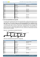
Table 30.10. Three Opamp Differential Amplifier Configuration
OPA OPA bitfields OPA Configuration
OPA0 POSSEL POSPAD, DAC0
OPA0 NEGSEL UG
OPA0 RESINMUX DISABLE
OPA1 POSSEL POSPAD, DAC0
OPA1 NEGSEL UG
OPA1 RESINMUX DISABLE
OPA1 NEXTOUT 1
OPA2 POSSEL OPATAP
OPA2 NEGSEL OPATAP
OPA2 RESINMUX OPA1INP
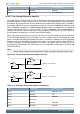
30.3.2.9 Dual Buffer ADC Driver
It is possible to use OPA0 and OPA1 to form a Dual Buffer ADC driver as shown in Figure 30.10 (p.
734) . Both opamps used can be configured in the same way. The positive input is configured by
setting the 0PAxPOSSEL to PAD and the negative input can be connected to the resistor ladder by
setting OPATAP in DACn_OPAxMUX. The output from the opamps can be configured to connect to the
ADC by setting OUTMODE to ALT or ALL in DACn_OPAxMUX.
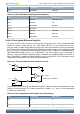
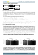
Figure 30.10. Dual Buffer ADC Driver Overview
R1 R2
VIP
-
+
VOUTP= VIP(1+ R2/R1)
or
VOUTP = VIP (Unity Gain)
VOUTN= VIN(1+ R2/R1)
or
VOUTN = VIN (Unity Gain)
R1 R2
VIN
-
+
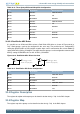
Table 30.11. Dual Buffer ADC Driver Configuration
OPA OPA bitfields OPA Configuration
OPA0 POSSEL POSPAD0, DAC0
OPA0 NEGSEL OPATAP
OPA0 RESINMUX VSS
OPA1 POSSEL POSPAD1, DAC1
OPA1 NEGSEL OPATAP
OPA1 RESINMUX VSS
30.4 Register Description
The register description of the opamp can be found in Section 29.4 (p. 710) in the DAC chapter.
30.5 Register Map
The register map of the opamp can be found in Section 29.4 (p. 710) in the DAC chapter.