
User manual


...the world's most energy friendly microcontrollers
2012-04-24 - Giant Gecko Family - d0053_Rev0.96 731
www.energymicro.com
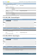
OPA OPA bitfields OPA Configuration
OPA0 NEGSEL OPA0TAP
OPA0 RESINMUX NEGPAD0
OPA0 NEXTOUT 1
OPA1 POSSEL POSPAD1
OPA1 NEGSEL OPATAP
OPA1 RESINMUX OPA0INP
OPA1 NEXTOUT 1
OPA2 POSSEL POSPAD2
OPA2 NEGSEL OPATAP
OPA2 RESINMUX OPA1INP
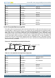
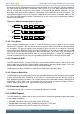
30.3.2.6 Cascaded Non-inverting PGA
This mode enables the opamp signals to be internally configured to cascade two or three opamps in non-
inverting mode as shown in Figure 30.7 (p. 731) . In both cases the negative input for all opamps will be
connected to the resistor ladder by setting the OPAxNEGSEL bitfield to OPATAP. In addition the resistor
ladder input must be set to VSS or NEGPADx in the OPAxRESINMUX in DACn_OPAxMUX. When
cascaded, the positive input on OPA0 is configured by the OPA0POSSEL bitfield. The output from OPA0
can be connected to OPA1 to create the second stage by setting NEXTOUT in DACn_OPA0MUX. To
complete the stage, the OPA1POSSEL bitfield must be set to OPA0INP in DACn_OPA1MUX. Similarly,
the last stage can be created by setting NEXTOUT in DACn_OPA1MUX and OPA2POSSEL bitfield to
OPA1INP in DACn_OPA2MUX.
Figure 30.7. Cascaded Non-inverting PGA Overview
R1
R2
VIN
-
+
VOUT1= VIN(1+ R2/R1)
VOUT2= VIN(1+ R2/R1)
VOUT3= VIN(1+ R2/R1)
R1
R2
-
+
R1
R2
-
+
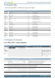
Table 30.6. Cascaded Non-inverting PGA Configuration
OPA OPA bitfields OPA Configuration
OPA0 POSSEL POSPAD0, DAC0
OPA0 NEGSEL OPATAP
OPA0 RESINMUX VSS, NEGPAD0
OPA0 NEXTOUT 1
OPA1 POSSEL OPA0INP
OPA1 NEGSEL OPATAP
OPA1 RESINMUX VSS, NEGPAD1
OPA1 NEXTOUT 1
OPA2 POSSEL OPA1INP