
User manual

...the world's most energy friendly microcontrollers
2012-04-24 - Giant Gecko Family - d0053_Rev0.96 705
www.energymicro.com
• Output to ADC
• Sine generation mode
• Optional high strength line driver
29.3 Functional Description
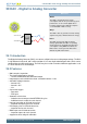
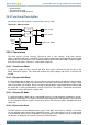
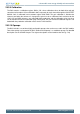
An overview of the DAC module is shown in Figure 29.1 (p. 705) .
Figure 29.1. DAC Overview
DACn_OUT0
DACn_OUT1
Ch 1
VDD
1.25 V
2.5 V
CH0DATA
CH1DATA
ADC and ACMP
REFSEL
Ch 0
29.3.1 Conversions
The DAC consists of two channels (Channel 0 and 1) with separate 12-bit data registers
(DACn_CH0DATA and DACn_CH1DATA). These can be used to produce two independent single ended
outputs or the channel 0 register can be used to drive both outputs in differential mode. The DAC supports
three conversion modes, continuous, sample/hold, sample/off.
29.3.1.1 Continuous Mode
In continuous mode the DAC channels will drive their outputs continuously with the data in the
DACn_CHxDATA registers. This mode will maintain the output voltage and refresh is therefore not
needed.
29.3.1.2 Sample/Hold Mode
In sample/hold mode, the DAC cores converts data on a triggered conversion and then holds the output
in a sample/hold element. When not converting, the DAC cores are turned off between samples, which
reduces the power consumption. Because of output voltage drift the sample/hold element will only hold
the output for a certain period without a refresh conversion. The reader is referred to the electrical
characteristics for the details on the voltage drift.
29.3.1.3 Sample/Off Mode
In sample/off mode the DAC and the sample/hold element is turned completely off between samples,
tristating the DAC output. This requires the DAC output voltage to be held externally. The references
are also turned off between samples, which means that a new warm-up period is needed before each
conversion.
29.3.1.4 Conversion Start
The DAC channel must be enabled before it can be used. When the channel is enabled, a conversion
can be started by writing to the DACn_CHxDATA register. These data registers are also mapped into
a combined data register, DACn_COMBDATA, where the data values for both channels can be written
simultaneously. Writing to this register will start all enabled channels.